


By Phil Wicks
For those that visit this site regularly you will have noticed that I am rather fond of the F1 genre, especially from the late fifties to the early seventies. During these years the cars were not particularly quick compared to some sports car classes. They started off as a 2.5 litre class which saw them through the fifties, but in the early sixties the FIA changed the engine specs to 1500 c.c. !!
It took the class almost five years to reach the old lap times of the early sixties and by this time most sports cars were circulating tracks far more quickly than the F1 class. The FIA reviewed the situation and with another formula change the 1966 cars were allowed the option of a 1.5 litre supercharged engine, or a 3.0 litre naturally aspirated engine. With several teams wrong footed and unprepared, the 1966 season saw a hotchpotch of motors on the grid. Eventually the Cosworth V8 DFV became the benchmark and every body who wasn’t running Cosworths had to play catch-up.
Among those who were caught in the engine dilemma was Lotus. They had tried a variety of motors after Coventry Climax had let them down and were looking at the BRM engine quite seriously, but they found its reliability frustrating. Eventually they too adopted the DFV with great success.

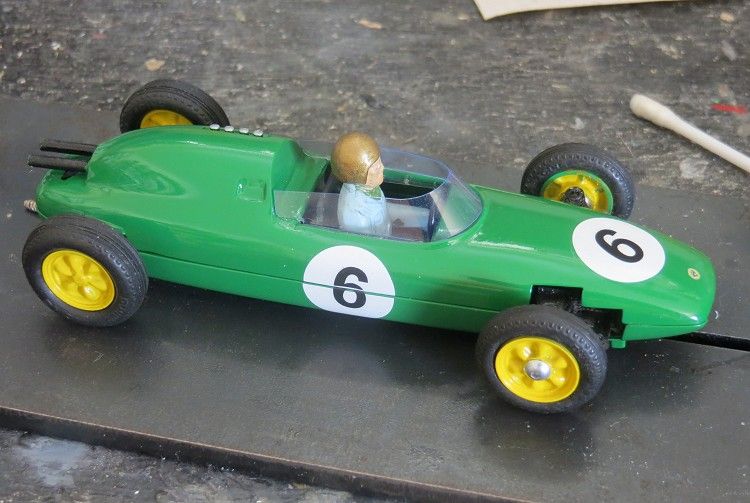
The lotus 24 and 25 chassis were actually produced at the same time. The difference being that the 24 was a space frame and the 25 a monocoque. Suspension was virtually identical and both would take similar motors. Although the legendary Jim Clark had driven the 24 in competition, it was the 25 that would give Lotus the constructors world championship for the first time in 1963, while the 24 was sold as a ‘customer’ car for several formulas.
‘60’s F1 GP rules!
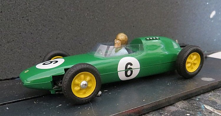
Airfix had a brief career in slot cars and at the time were reasonably successful in the UK and some parts of Europe. Their success was reflected in their purchase of the MRRC company in the mid sixties which went on to become another lonely manufacturer in the wilderness years of slot racing in the ‘70’s. But the Airfix I loved as a very young boy were the early sixties models, especially the F1 cars. I have in recent years managed to pick up some mint condition kits and spares and have been fortunate to assemble quite a respectable stable of Airfix racing models, including some of the rarer cars, but with an urge to build even more, it soon became obvious that those who had the kits new their worth, and weren’t about to let go of them for peanuts!
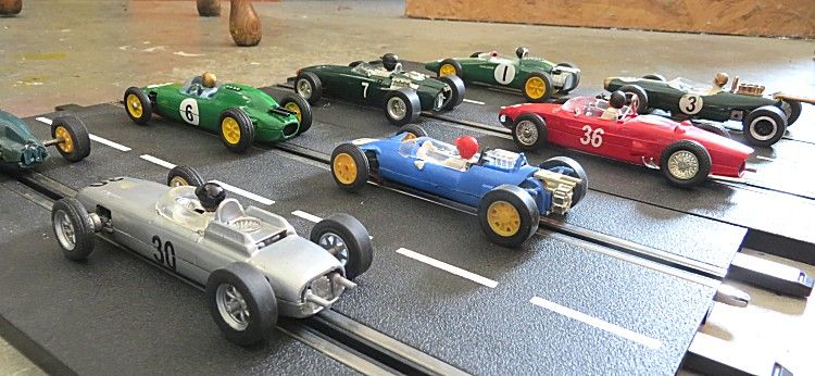
Supershells, Scalextric and Airfix grid
Easy enough to find though are Airfix models in the spares and repairs section of eBays slotcars. This search will reveal a whole variety of slotcars in various states of dismemberment, and a few Airfix models that are looking for some TLC! If you have a modicum of modelling skills, these model will not present too much of a challenge. One issue though is the old Airfix ‘Cube’ motor. This was never the best when it was new let alone fifty years old, and it will result in even more frustration getting them to work. The long braids present another problem but a bit of lateral thinking will see this overcome. My solution was to fit an HO motor from some of the older slotcars.
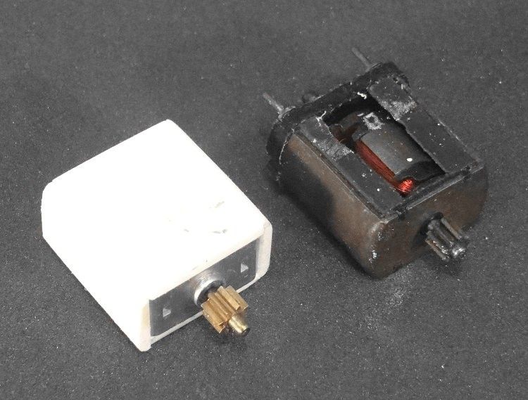
The HO motor from the Scalextric Fiesta XR2i is ideal for this and is not too hard to find. They too litter the spares and repairs section of ebay and if you shop around, there are several ebay shops selling the train version of the motor under the serial number X8202. But the motor on its own does need some attention. I firstly tried to wedge a motor in the old motor space but this wasn’t too successful as the pinion shaft needs to sit dead centre to the axle shaft. I then tried shimming it up and everything was just getting messy.
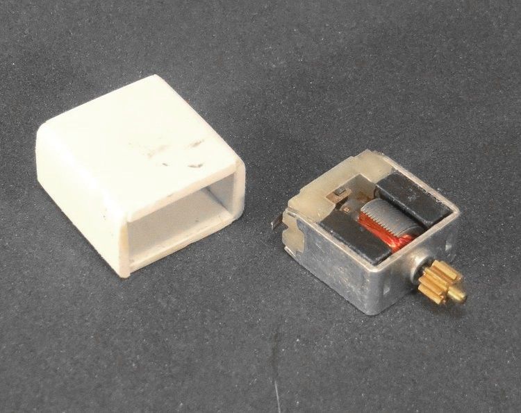
After some deliberation it occurred to me that the HO motor was smaller in all dimensions to the old cube motor so the solution then became obvious, to build a case which would hold the HO motor and fit directly into the motor mounts in the body shell, and, line up with the axle! After measuring up it was apparent that making a sleeve from plastic card was going to be the way. Some 2.0 m.m. card was cut to size and glued together around the HO motor, and after a couple of days the new sleeve was trimmed to length and sanded a little to size and before I knew it I had the new motor sitting smartly in the lower body half.
Again there was still work to be done but again, it was straight forward and a minor challenge. The motor sleeve had been sanded to the correct thickness but the body halves would not go fully together. This was caused by the corners of the sleeve not matching the radius of the body halves. A short period of sanding corners saw the sleeve fit more comfortably and eventually the body halves close without a gap. There are only two body screws on the model and with the front one on the far side of the steering cut outs in the bottom body half, it was not the best clamping moment around the motor and sleeve. At a later stage I did introduce a third mounting post behind the steering. This was to aid the clamping moment of the body halves and produce a firmer fit for the motor and sleeve.
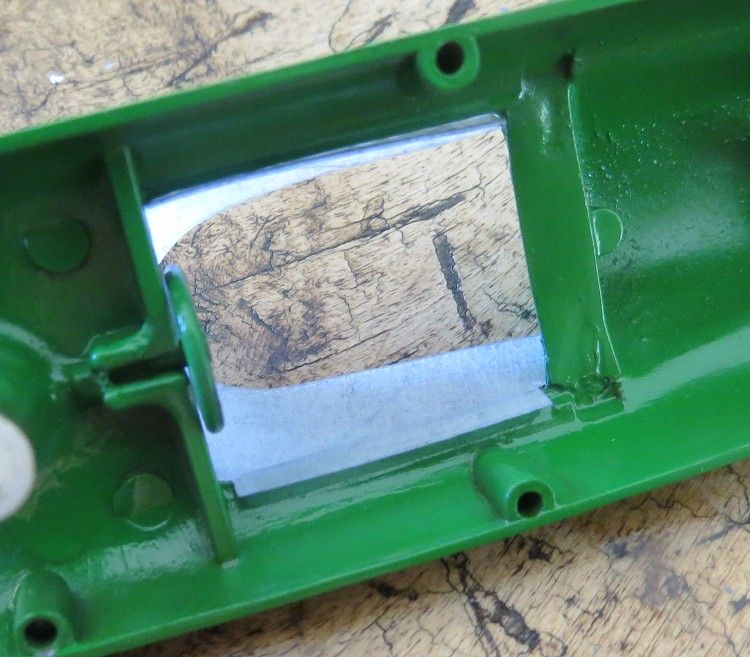
Next up was a suitable crown wheel and pinion as the s were not the best. The crown wheel was about 64 pitch and not the best to match up, and the pinion had the wrong diameter hole in it ! So a complete new gear set up was looking to be the fix. Where space had been an issue I had previously used some Slot.it 24z crowns on other models, and these come in a smaller diameter than the normal 27’s so that was the first choice. Next up was the pinion, and again, Slot.it have a useful 8z brass pinion which took my fancy; but at 2.0 m.m. the pinion hole was too large? Mmmmmmmmm?
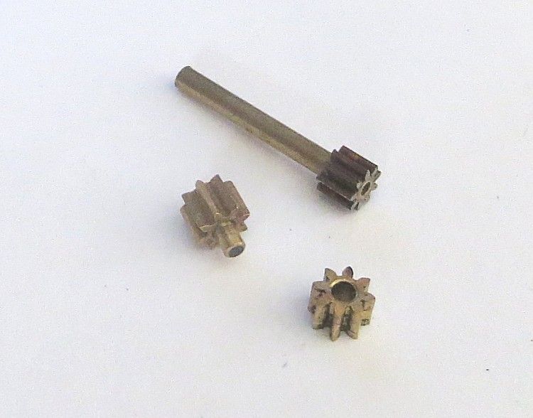
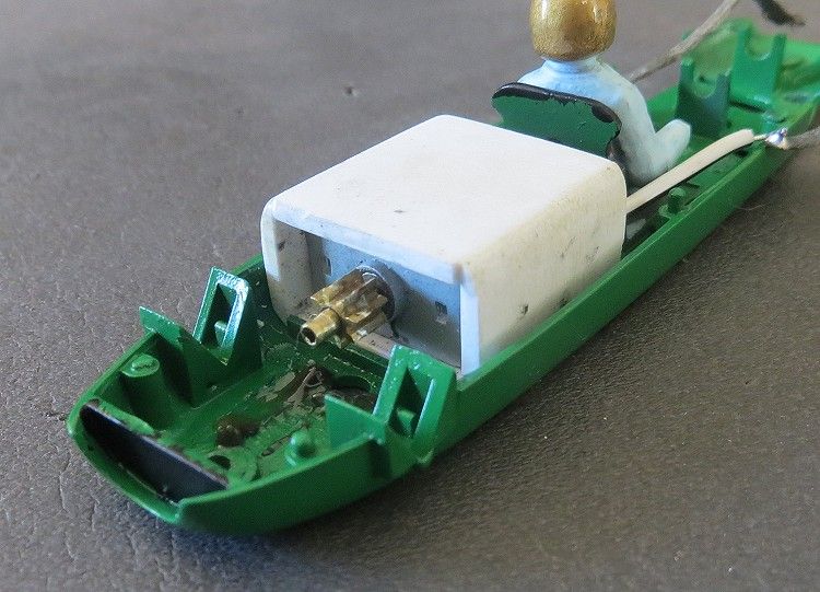
Anyway, soldiering on, I decided to come at the final drive from a different direction! The motor shaft was 1.5 m.m. dia. therefore rendering it not fit for the 2.0 m.m. centre slot in the contrate; and to compound the issue, it wasn’t long enough anyway, if I was going to use the motor mounting position then there had to be another option. Unbeknownst to me this was only a week or two away and I had decided to press on with the renovation and painting of the body. There was a windscreen to make and other bits to source.
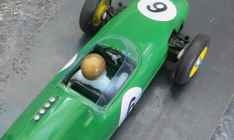
How good is that screen!
On a trip out to my local hobby supplier http://www.hobbyparts.com.au I noticed some fine bore brass tubing in the hobby metals section. This had an outside diameter of 2.0 m.m. and a wall thickness of 0.225 m.m. ? Mmmmm. The outside diameter was fine and a bit of mental arithmetic was called for, .225 x 2 was .450 ? Mmmmm? 2.0 - .450 was......1.550 MMMmm! So the tube had a centre bore slightly larger than the motor shaft, 0.05 m.m. to be exact. Would it do, drop of supaglue?? As it happened, the tube was an interference fit in the pinion, this had the effect of compressing the tube and loosing the 0.05 slack!
The tube was cut longer to allow it to penetrate the axle centering gear slot and the pinion was presses on one end of the tube. The tube was now barely a sliding fit on the motor shaft. The Shaft was cleaned and scored lightly to give the glue some bonding help and after applying the merest of a spot of glue, the shaft and pinion were pressed on to the pre determined marks on the motor shaft. Et voila! one 8z pinion on an HO motor with a 2.0 m.m. output shaft, thus killing several birds with the one stone! Flushed with success it was time to move on!
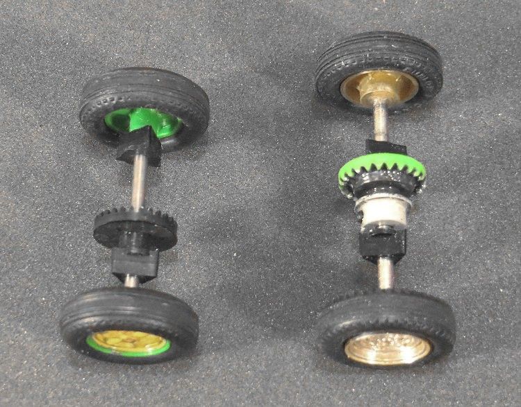
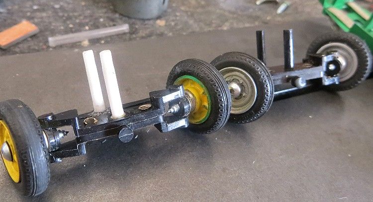
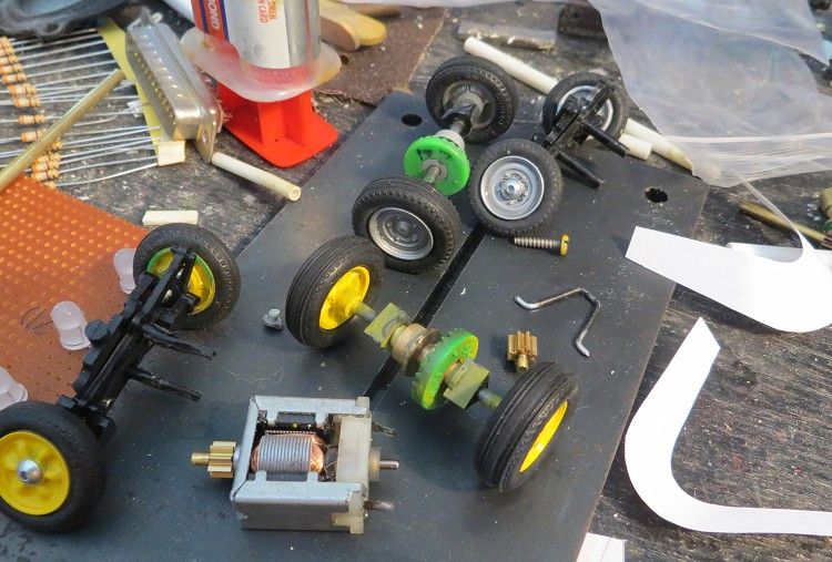
The Airfix models came with quite a weighty and somewhat sluggish motor and with such it wasn’t necessary to pay too much attention to some basic chassis tuning standards such as wide track dimensions. The model has quite a narrow track both front and rear so being an opportunist I decided to widen it a bit just to give it a bit more stability. A new axle was cut from music wire and I decided to retain the axle bearing ‘v-blocks’ and the wheels just because I wanted to. The front wheels had a couple of shims cut and mounted behind the wheels just to pump them out to the rear axle’s new dimension.
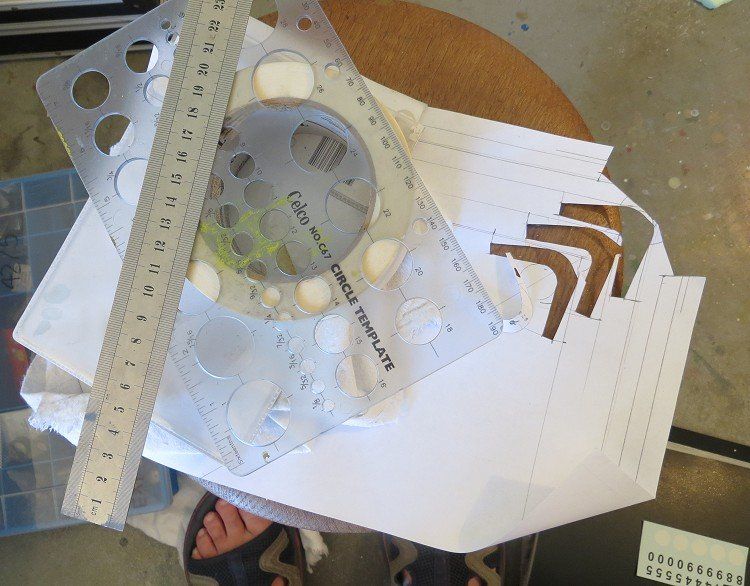
Another hurdle was the windscreen. This I wanted to look good as I had already made several for other models and had never been 100% happy with them. The secret was to get it right on paper first, which I hopefully did. I have a circle template which I have used with some success, so I decided to persist with it and spend a bit more time getting things right. A right angle was drawn on a sheet of copier paper and an arc with a larger radius than the screen (28 m.m.) was drawn in the corner. The depth of the screen was marked and a second arc about 4.0 m.m. smaller was scribed to this second mark.
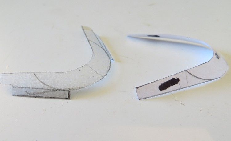
The length of the sidescreen was measured and drawn on the plan slightly longer than needed, to allow for trimming to fit if necessary. The screen was then cut from the paper and applied to the model. The first attempt was not great but by adjusted dimensions and changing angles, after several attempts, I eventually achieved a screen which was a good fit. Next up was to make this in PET. My trick was to stick some masking tape to a sheet of PET from an old bubble pack and then repeat the process of marking out the screen on the tape. Care was taken when cutting it out as it will be hard to finely trim the shape after it’s cut. Once cut, the tape was removed to reveal the plastic screen.
To help anchor it to the body I created a couple of strips along the bottom of the template before cutting. Once cut, these strips had some small holes drilled in them to give the fixing epoxy a lasting key. The screen was held in place while a bead of clear epoxy was painted along both sides of the inside with a fine paint brush. The screen was that good a fit that it stayed in place without support. The body top was left to one side to dry.
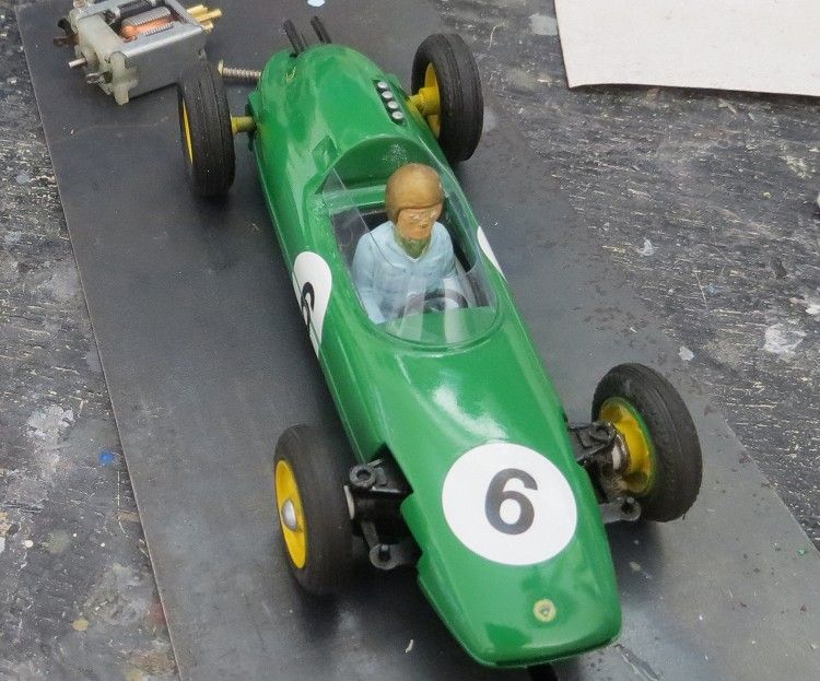
As the model came slowly together it was just a case of basic modelling skills required to finish it off. The rear end of the model had taken a hit sometime in its former life so the body had to be repaired and the exhausts replaced. The exhausts were made from small bore brass tube cut to length and fixed on the inside of the upper body with supaglue.
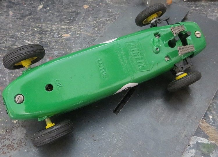
I decided against the full length braids which run inside the model up to the motor and substituted most of the braid with a simple wire. It is essential though that the braids return inside the model up to the little clips in the floor; this will help keep the braids stable when it is running. Another important mod is to carefully widen the slots in the floor pan which the braids pass through. I have used Slot.it tinned braid for the simple reason that there is not a lot of weight in the front of the model and the soft braid will follow the undulations of the conductor rails or strips more accurately.
Always have more than one job on the go!
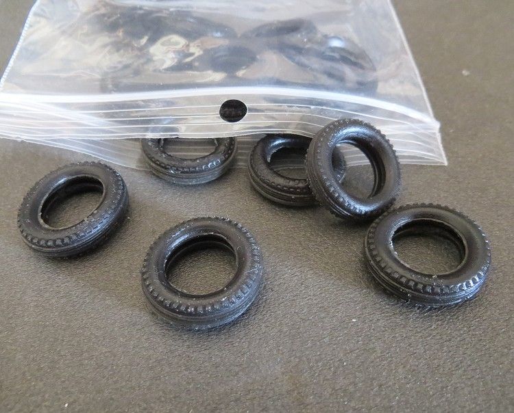
As of this moment the only thing I am waiting for is some rear tyres. The s are fairly hard and although there is a little grip available it would be nice to have some scale urethane tyres. The model goes together well and with the aid of the extra screw behind the steering is quite solid. On the local ferrador surface it has plenty of grip and the model drives about NC1 speed and is very pleasant to drive. If it is pushed too hard it has a tendency to lift out of the slot at the front, which doesn’t surprise me, as the motor is a bit more lively than the . With the voltage down it behaves impeccably, but, for 12 volts I may need to consider some extra weight at the front end.

I always maintain that you should always have more than one project on the go at a time, This removes the temptation of handling the model while both glue and paint might not be ready for handling. I use the term ‘cured’ quite often as I believe paints and glues may set in hours, but they need to cure (at least 24 hours) before they are safe to handle. Dry but uncured paint will pick up fingerprints if handled too soon. Glues will also become detached if too much stress is put on them too soon after drying; and always make sure that all non polystyrene glues get help keying to plastic. This can be achieved by ‘cross hatching’ the surfaces to be glued with the tip of a sharp modellers knife.
So if you like this article, do yourself a favour and give it a go. All the materials should be available at any good hobby store and the rest will be up to you.
Good luck