


.
.
By Phil Wicks
But a chassis is a chassis and for those models built there was a period of adaptisation which saw them compete both at home and internationally at a wider level. As ever, Colin had a personal hand in the design of his cars and it must be said that more than several of his drivers over the years had concerns abut the safety of the design of his cars, with good reason, to the point where his engineer disowned some of the models produced. In the sixties Lotus had a reputation amongst its peers as an unsafe car and indeed on more than several occasions they suffered structural failures at speed on the track.
The 30 was also dogged by this. Lotus (read Colin here) had decided to opt away from the traditional space frame construction for this model and go for a more revolutionary centre spine chassis; and on occasion the Ford V8 engine coupled to the ZF transmission proved too much for the main load bearing parts of the chassis; but it must be said that when the chassis, engine and gearbox did hold together, the 30 was incredibly quick!
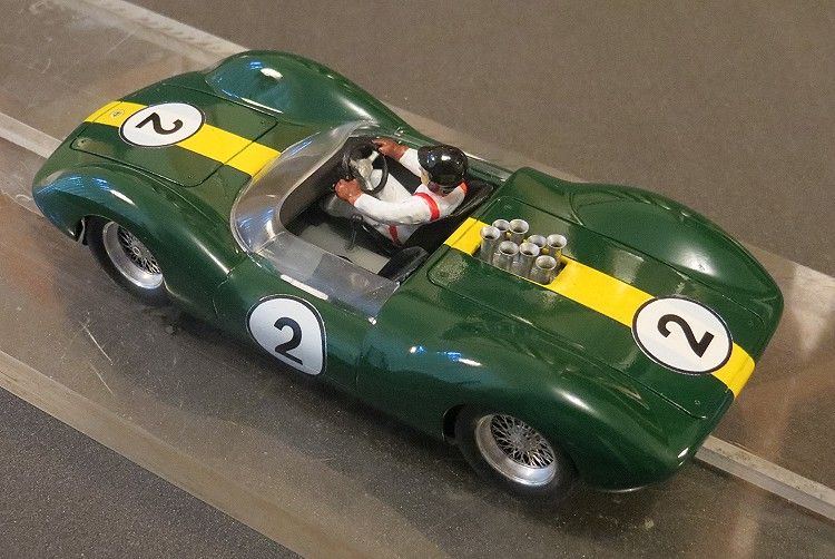
'Pink Stamps' Lotus 30
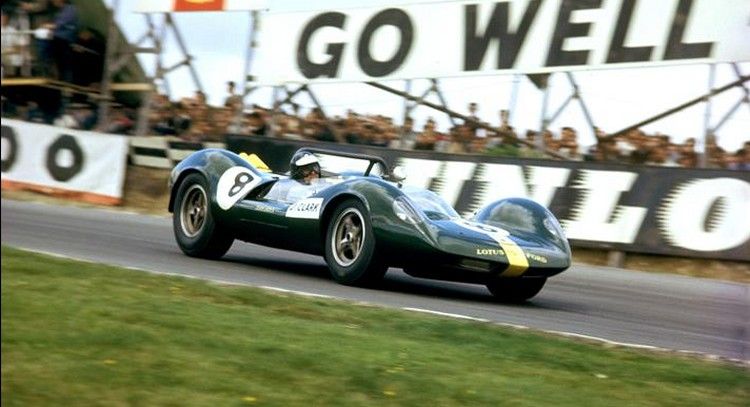
Lotus soldiered on with the 30 and legend Jim Clark managed some results with it before it was replaced by the 40 which had uprated wheels and brakes among other features. Call it a learning curve if you will, but the idea of the forked chassis, ly used on the Elan, with all its faults, did successfully carry over to the road going Europa and Esprit models, albeit with smaller engines.
Lotus 30 footage
On the track the cars eventually became overtaken by sheer weight of numbers. The Chevrolet ‘big banger’ engines of 6 litres and more became popular with the opposition and the 30’s very soon became outclassed. At the time, the 30 (& 40) where probably the biggest Lotus sports cars ever made. Records show that there were 23 series 1’s produced and 9 series 2’s. Sadly there are few left in track condition and the whereabouts of many remain unknown, possibly in museums or private collections.
Lotus 30 - Bonham's auctions
Tamiya have made the effort at some time in the past to reproduce the Lotus 30 reasonably accurately. I say reasonably because it is obviously not based on a particular model, much like models are today, but more a general rendition of the model based on available information at the time of design and manufacture. All in all a nice model but very basic for the beginners market.
For the purpose of this build I have committed sacrilege in the eyes of the geeks and nerds and I too have not reproduced a particularly historic scale model in accurate detail but have been more inclined to produce a model which is pleasing to the average eye and contains nice touches which cause the casual observer to smile a little and think ‘that’s nice’. So, bearing that in mind, let us wander down the road of scratchbuilding and see what I have done with what I have.
This is the second 30’ I have built, the first being a Hawk kit from the sixties which made a very nice slotcar (see scratchbuild section) which was a square brass tube chassis propelled by a low speed ‘S’ can type motor from the local electronics store. Inspiration this time came from my Airfix restoration exploits. I had acquired some HO motors of reasonable power which have transformed some otherwise scrap models into re-usable slotcars.
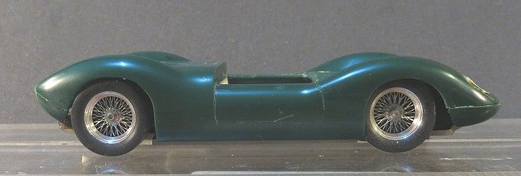
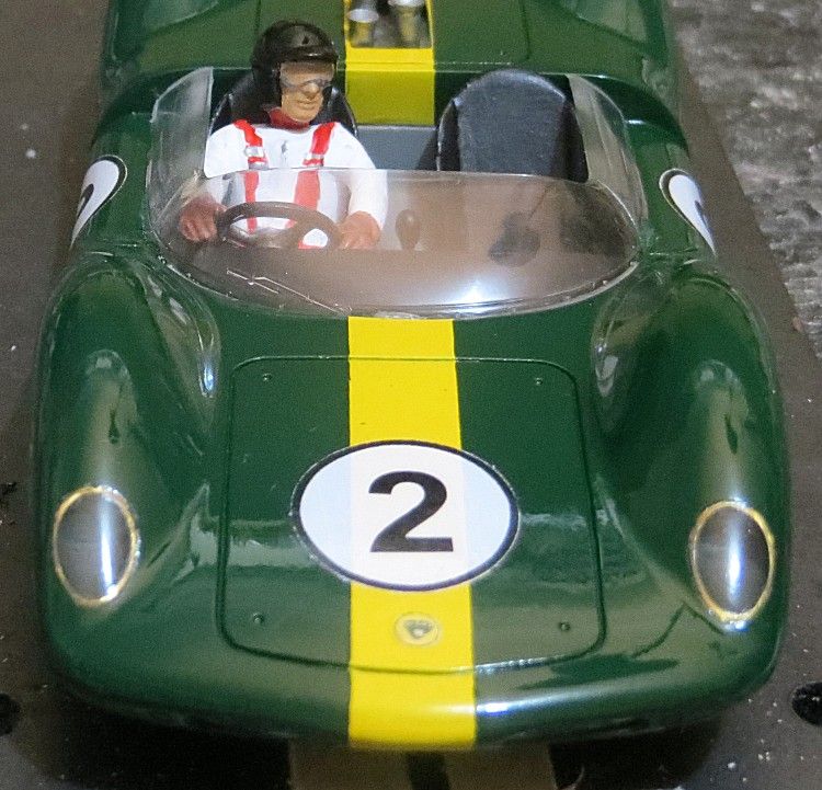
The motor is about NC1 power and although it doesn’t have the zip it has the top end making it a nice cruiser which you can spend lengthy periods of time just touring your local home circuit. The body is very basic but Tamiya have excelled themselves by producing a very usable body and exceptional screen, the rest I can do.
As always there is a procedure which must be followed to ensure things go together in the right order. It will also prevent essential works being carried out on a model which has just been glued or painted and I must state here that if you do glue or paint something during construction, ensure you have left at least 18 hours between operations to allow glue or paint to dry and cure. First job is to build a chassis and assemble the front and rear axles, and to make sure everything will slot together neatly on assembly. If you are a regular to the Outhouse you will see some old tried and tested features which have all come together on this model.
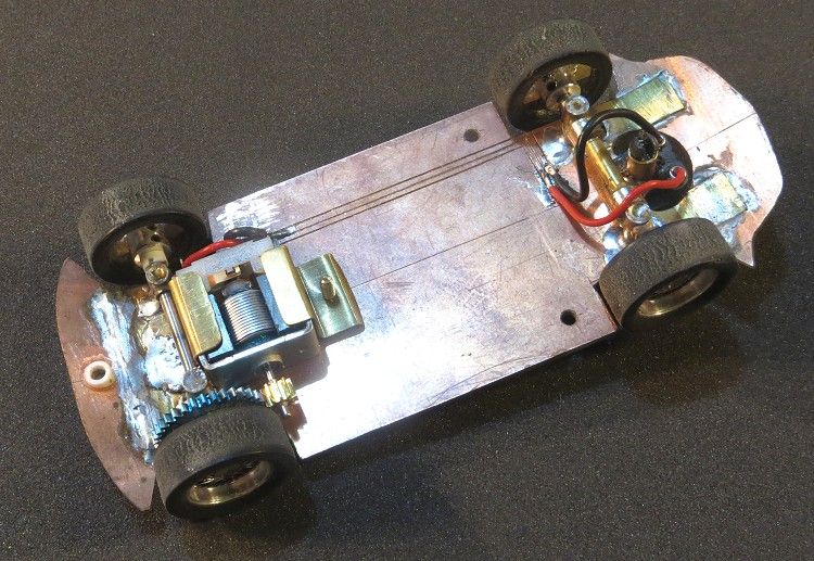
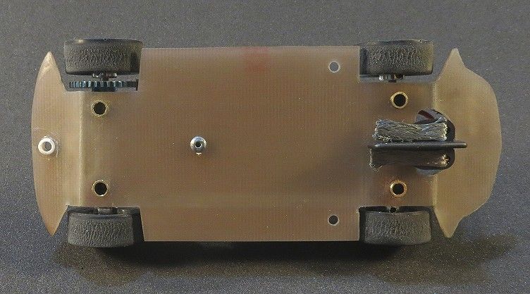
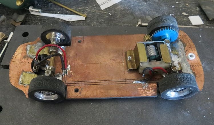
First up the front and rear valances had to be glued to the model. I need this done to allow me to get dimensions for the chassis. The chassis as always is made from PCB material. This helps me secure all components in place with a dab of the soldering iron. The PCB material was marked out according to the dimensions of the body and the front and rear of the chassis were cut and folded up to match the inner edges of the valances. Once established, the turn-ups were superglued into position to hold them in place. I then soldered a couple of thin brass plates across the turn ups just to ensure they don’t break away at some later date.
After fabricating the basic chassis it is then necessary to locate the wheel and axle mounts. The axle dimensions (with wheels and tyres attached) need to be measured at the inside of the tyres. The centreline for the axles is scribed and the chassis is marked so the wheels will have good clearance from the PCB chassis material; also, the wheel wells in the chassis need to finish neatly where the body starts either side of the wheel arch. The mounts will be the intersecting tube type as used on a lot of my models to date, and it is essential that these are located in the correct position to ensure the wheels appear in the centre of the arches. If you do drill them slightly out of align you can adjust them slightly by tipping them forward or backward in the holes to achieve perfect alignment before spot soldering them.
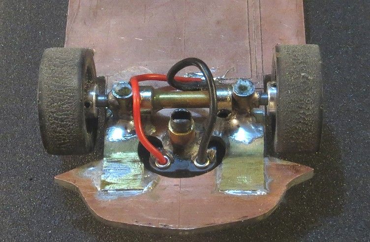
On this model the chassis will require the rear to be cut to fit the sidewinder setup and to allow the extra clearance for the spur gear on one side. This is done after the wheel well and axle mount positions have been established. I haven’t worried too much about the motor position at this stage as I know the HO motor will have adequate space under the rear of the body without intruding into the cockpit.
The guide tube and cutaway can now be measured and cut. I try not to do too much fine wok with the dremel as I have over cut things in the past, so I always finish of with a set of small hobby files. Once the axle mounts and axle heights are established and the guide tube is mounted, the ‘wixle’ assembly can be made and fitted to the front. For newcomers this is a method I have developed to allow the front wheels to rotate independently of each other while still holding them in line with each other. A bit like the Fly front stub axles without all the flop! (check out the Cortina scratchbuild in this section for more detail on axle mount construction).
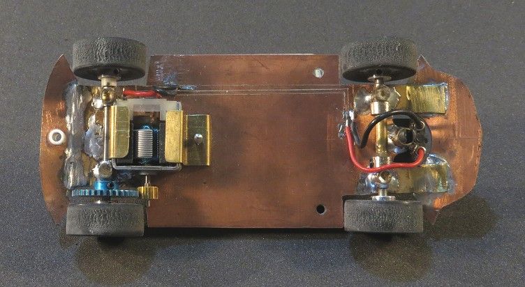
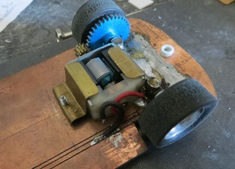
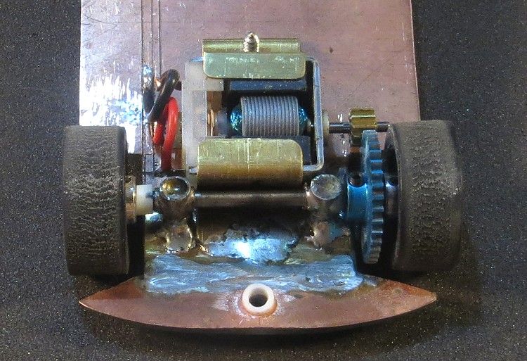
From the chassis perspective the last job is to mount the motor. I have chosen a 3:1 final drive and the gears have been fitted to the motor and axle. The motor is slid up to the axle from the front until it is in a snug mesh with the spur gear. I have then lightly scored around the motor and left a mark onto the copper face of the PCB. This will help me determine the motor clamp positions. The motor will have a permanent clamp at its rear and a detachable one at the front.
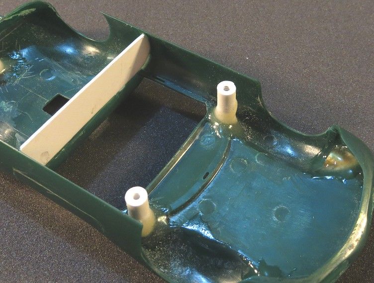
Next I needed to get the chassis fixed into the body and again some of my best tricks were used. The mounting posts were made from polystyrene tubing cut to length. Three fixing holes were strategically drilled in the chassis and the posts screwed on the chassis over these holes. The chassis was lowered into the body and by a slow process of elimination the chassis was removed and the posts trimmed and the fit tried again. Eventually I got it so that the chassis was a flush fit with the lower edges of the body. Once achieved, the ends of the posts and the points in the body where they would fix were scored with the tip of a hobby knife.
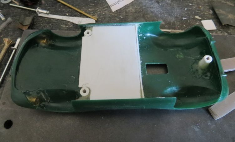
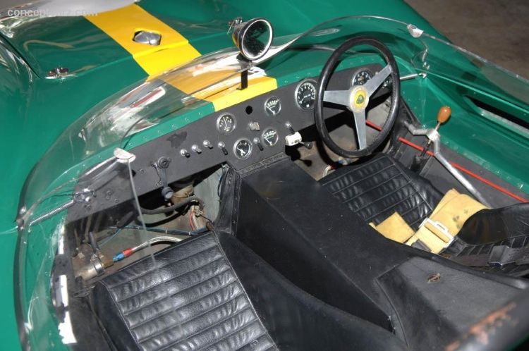
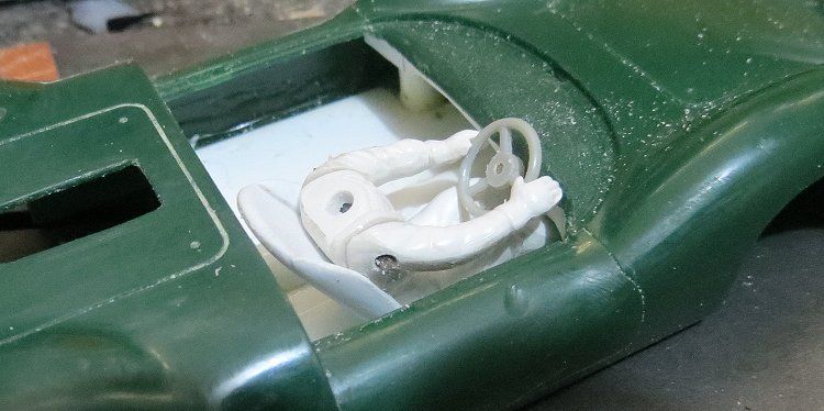
Extra strength epoxy was applied to the posts and to the body points and the chassis was lowered carefully into the model. Once all the levels were correct, the body was left to one side for a couple of days to set and cure. At this stage I started to assemble the cockpit. This was made simply from some thin gauge polystyrene sheet and the floor and back were soon made. On the real car there are fuel tanks inside the side pods where the doors would normally have been on other cars but I chose not to go into this detail. A shallow dash was made and glued in place under the dash board.
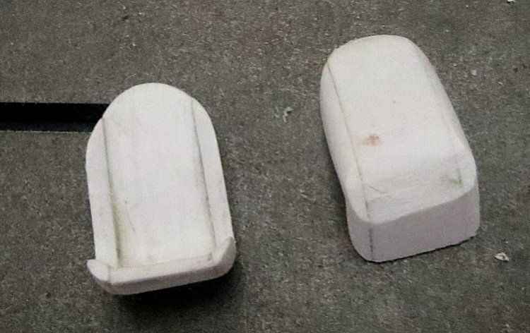
Next up were the seats. Now the seats depend on the driver and the driver depends on the seats! And as the model came with neither, the two had to be developed together. I had a driver in the spares box but he was all the wrong shape; so, a seat was needed to get him in the right position.
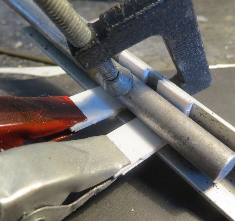
I made the seats by laminating some plastic sheet. I cut a couple of strips of 1 m.m. polystyrene sheet 10 m.m. wide and worked out what length would be required to make a half decent seat. Once established, two strips were cut off and glued together and placed in a piece of alloy angle. While the glue was still wet the handle of a hobby knife was placed against the strips and then I screwed a small clamp against them. This had the effect of holding the strips in place in a 90 degree ‘V’ about one third the way along the strip. Once dry and cured I had the basis of a seat.
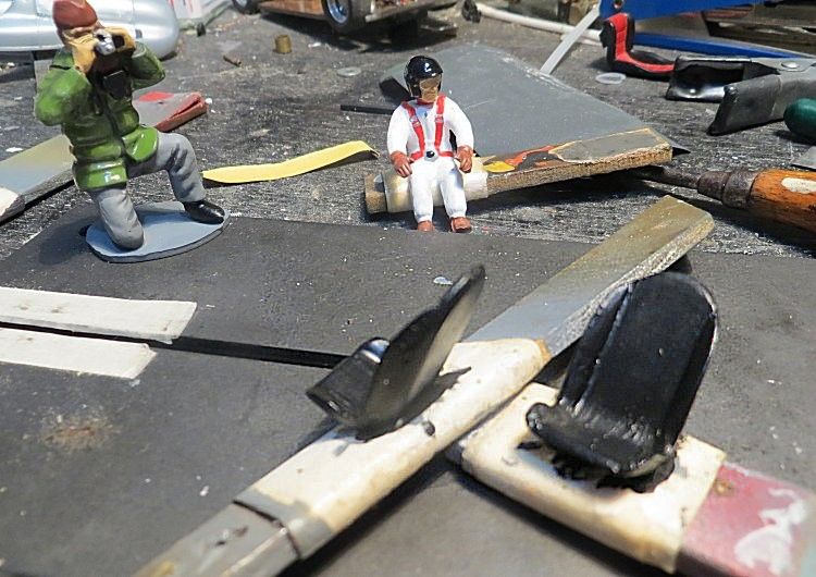
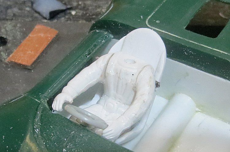
Pieces made of two m.m. styrene were glued to the seat sides and again once dried for a day or two the sides were shaped into the contours of a racing bucket seat by scraping the excess and unwanted material with the edge of a modelling knife. The rest of the seat back was fashioned and eventually the driver took its turn to be remodelled. An important factor was that the driver needed to fit snugly into the seat and not appear to perch precariously on top of it. This was achieved by scraping and grinding away all the parts of the driver which were going to remain hidden until he sat firmly and deeply, and more importantly, lifelike, in the seat
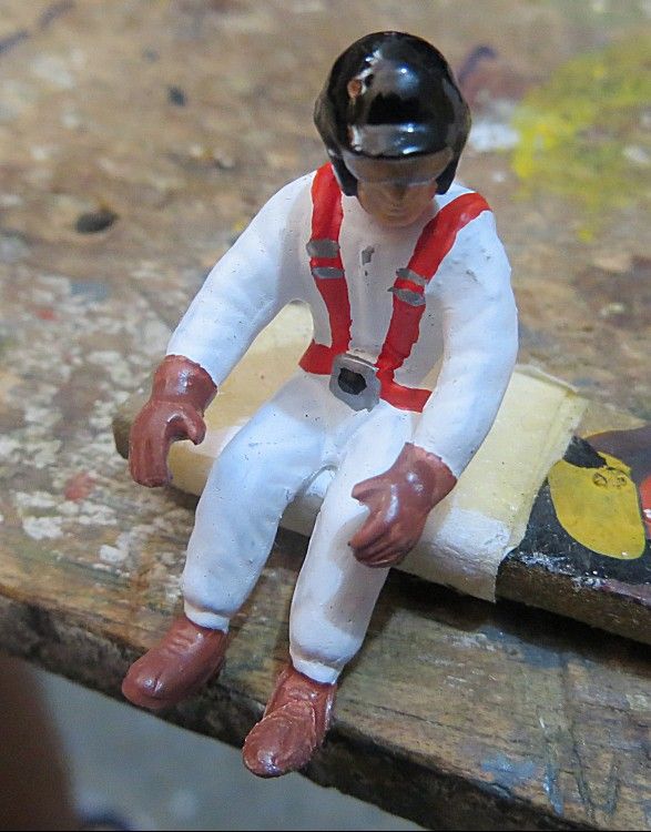
The seat base needed flattening to fit the floor pan in the model and this was achieved by sanding it on some coarse aluminium oxide paper, about 80 grit, to give it a coarse texture for keying when glued. This process was a trial and retrial in order to get the seat at the right angle, the driver in the right position and the whole positioned with the steering wheel in one side of the cock pit. With everything hinging on the shape of the driver, the driver then needed to be reshaped!
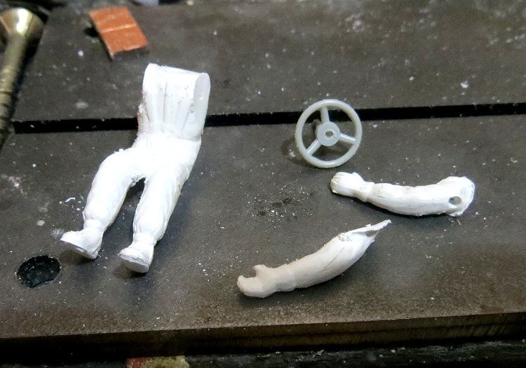
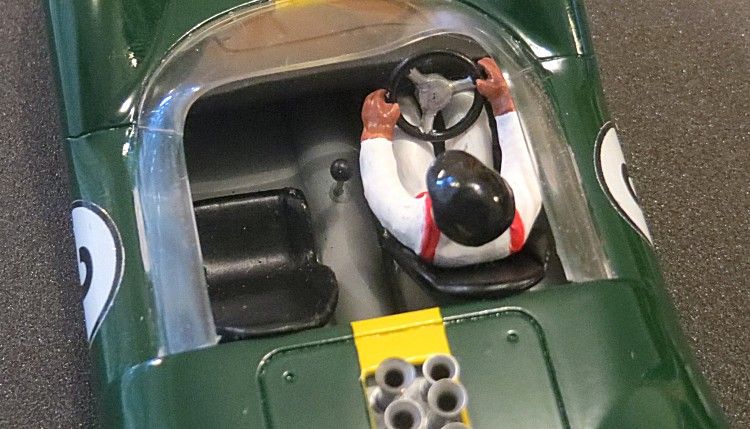
A 1/16th hole was drilled through the driver from shoulder to shoulder!! Both arms were then cut off neatly at the shoulders with a razor saw!! A piece of 1/16th brass tube was then fitted through all the pieces and the driver rested in position in the seat, with the steering wheel, in the cockpit. After some fine tuning and several adjustments later I applied some drops of superglue to the shoulder cuts; just enough to hold the arms in place once removed from the model. Once removed, the gaps were topped up several times with superglue until they were completely filled. Some light sanding and mould flash scraping saw the driver ready for painting.
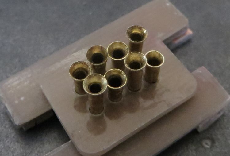
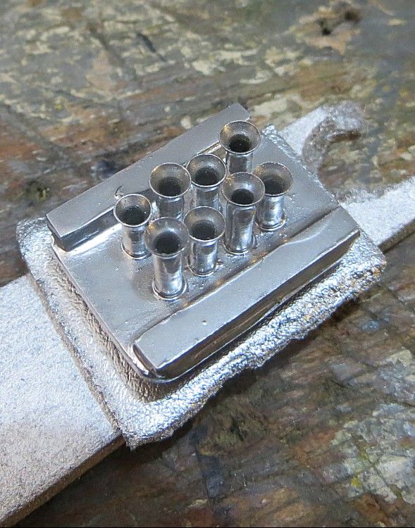
While all this has been going on I decided to make some ram tubes for the intake. Not content with a simple bunch of eight, I decided to stagger the heights as per the McLaren M20 and other cars of the era. Not true Lotus 30 but who can say it never happened? Mmmmmmmm? Basically, the pipes are small bore brass tubing; the end of pipe is flared with a small steel mandrill and the pipe cut off to length.
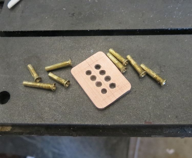
After doing this eight times a small piece of PCB is cut a little larger than the opening in the rear bodywork. This is carefully measured, marked and drilled and the pipes set in it and soldered. I used a home made gauge to make sure the pipes were all at the correct height, doing the shorter ones first. When soldered together they had a coat of ‘bright chrome’ straight from the tin, and a couple of coats of clear enamel for good measure.
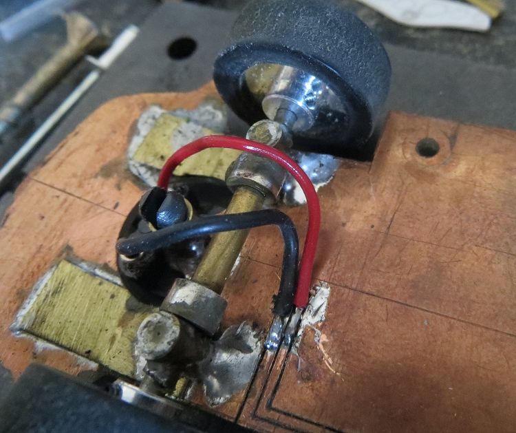
Back to the chassis, and the last job on the chassis is to get the power to the motor. Because the model is going to have a full interior I wanted to avoid faffing about with loose wires when removing and fitting the body in future. To overcome this I have scored through the copper and created a couple of conductor strips from front to rear. It is a simple process then to just solder the lead wires to the front of these strips and the motor wires at the rear, leaving the area around and under the cockpit free!! Finally, once happy with all the heights and settings, the axle mounts and guide tube are soldered permanently in place.
Before we consider painting we need to get the body as near to complete as we can. This means all the other details which need making and gluing and painting need prioritising so they are completed in the order they may be wanted in; and once again, we don’t want to be sawing, sanding, gluing and cutting painted items, they will soon end up looking pretty second hand! So preparation is the key word! One job was to ensure the screen popped into place effortlessly. Some light scraping around the base with a modeller’s knife achieved this, but it might need repeating once the body was painted
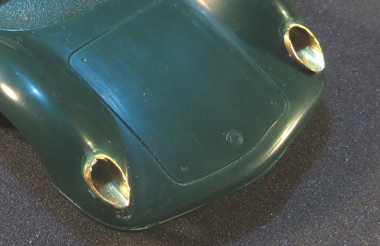
The final job before painting was the headlights. As with other models I decided to give the model 3D headlights instead of the vestigial lamps which ly appear moulded on the body detail. The lamp holes were drilled with a suitable drill in a small battery hand drill, and the drill was slowly lowered to the straight ahead position, this gave me the elliptical shape I would need to have realistic lamps. Once drilled, a length of snug fitting brass tube was sawn to length and roughly pre shaped before epoxying it in place in the body.
When set and cured the protruding brass was carefully dremelled then filed into the body shape. With both light shells in place I the similarly cut a length of clear plastic rod to size and glued this in place on both sides. I had already painted the insides of the shells silver and used clear epoxy to fix the plastic rod in place. Yet again, once dried and cured, the clear lamp lenses were also dremelled and sanded into shape. Before painting I carefully coated the headlamps with Humbrol ‘Maskol’, which is like a liquid rubber masking solution. After application it dries fairly quickly and can be sprayed over within fifteen minutes.
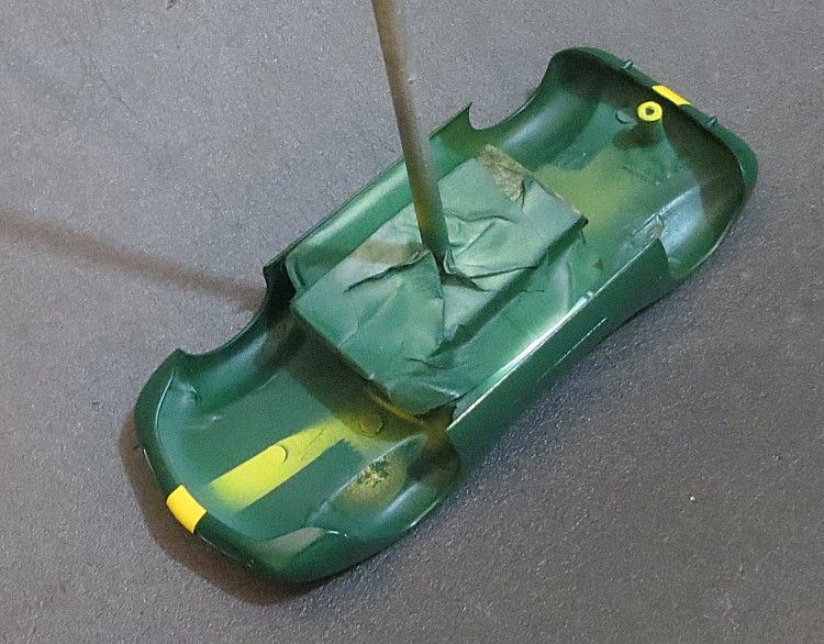
Now for the hard bit! I dread having to paint models because of the many pitfalls which can ruin a good pain job by not following the minimum of cleanliness procedures; spray gun, brushes, hands and fingers all need to be pretty clean every time you do paint work. If they aren’t you can guarantee something will go amiss and an ugly print or smudge will manifest itself on that pristine finish! So, whenever starting a process you may not be confident with, always have a dummy run on an old body and get it right first before moving on.
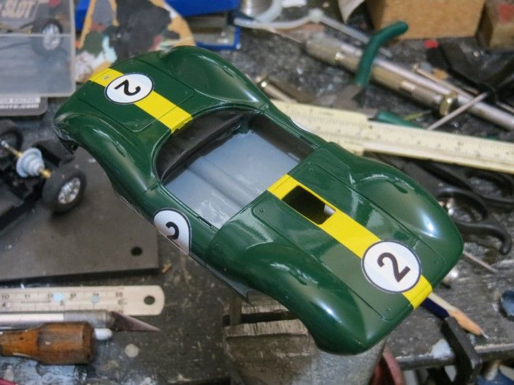
On this model I decided to glue the drivers cockpit in place early on in the piece so that things like driver position could be finalised. Next up I taped one of my painting sticks to the underside of the drivers tray to facilitate holding the model through the painting process. The body was primed with Tamiya acrylic ‘neutral grey’. Once set this is used to find the blemishes in the body work like the glued valances and other minor moulding dimples. After the blemishes were rectified the repaired areas had another coat of neutral grey.
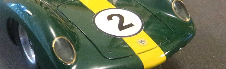
With the primer coat dried well I rubbed the whole model down with some coarse dry linen. This acts like a very fine wet and dry and leaves the primer coat with a very smooth finish. Next up was the body colour, in this case a slightly lightened dark green acrylic which was sprayed on fairly heavily but in one coat. Once that was dry the body was masked to take the yellow stripe. I used 6 m.m. Tamiya masking tape in a dispenser, this makes handling very easy; the inner edges of the masking tape were lightly brush coated with clear acrylic to seal them and prevent annoying bleed under the tape.
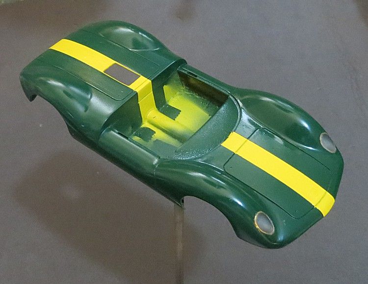
40 m.m. tape was then used to complete the masking process, applying it to the 6 m.m. and running it around the sides of the body to prevent overspray. Once masked the front to rear stripe was applied by spray gun and once set (1 hour), all of the masking tape was carefully removed. I used Tamiya flat yellow acrylic as it is a bright yellow and covers much better than the gloss acrylic, which can be watery. Again after all else has been cured the yellow got a rub down with linen.
Here I departed from convention. Having a model spray gun is a great help but it does have issues. The main one is keeping the interior of the gun clean, and the internal channels are not all accessible and frequent flushing with solvent is required. In my experience this is not a guarantee that all the old paint has been removed and on several occasions I have marred a perfect paint job after horrifying black specs have come from the gun, even after extensive cleaning. My solution is to revert to the good old spray can for clear finishing! And, I use Tamiya enamel!! I warm the paint in a bowl of hot water and warm the model under a table lamp, this will encourage the paint to level out and minimise the risk of an ‘orange peel’ finish.
At this stage the ‘Maskol’ masking on the headlights was removed carefully and the paint edges tidied with the point of a modeller’s knife. After giving the can a good shake the model is then sprayed from a distance of 300 m.m. or so, this is to prevent too heavy an application resulting in over spraying and annoying runs. Once the first clear coat is on I rotate the model under the table lamp (100W) for about two minutes. This prevents runs and helps the clear to gel to a level where it can be left to dry.
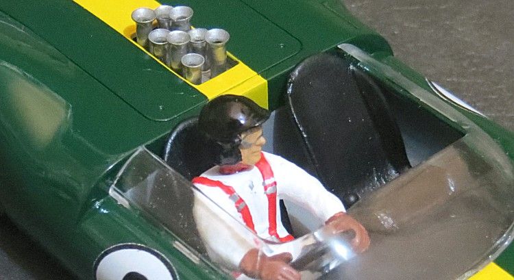
Almost there and penultimately, the decals are applied; these get a brushed on light coat of acrylic clear to protect them from what will be the final coat of enamel before they are floated off their backing paper. Applied in good time after coating, the model is then left for a day for everything to cure. Last up, the second coat of clear enamel is applied much like the first, we breath a sigh of relief and go and open a beer! But the final job is to glue the driver in his chair, with the steering wheel, into the cockpit! This is where three hands would have been useful! Also, the ram pipes had to go into the rear body. These are fitted from underneath and are ‘tacked’ in place with superglue and the tip of a modeller’s knife. The underside of the pipes have had a smear of full strength epoxy which will cure while the superglue holds them in place.
And finally, the screen can be fitted. This is a good quality screen and care must be taken not to get glue or paint on it; or at worst, crack it while fitting it. Even though the model hasn’t had a vast amount of paint on it, it will interfere with the smooth fitting of the screen. My solution was to carefully scrape around the lower edge of the screen where it fits into the body recess; again, as with other parts, this requires trial and testing until it clips snugly in position. To hold it in place I opted to put several spots of clear epoxy on the little tongues which fit through the body. Sorted!
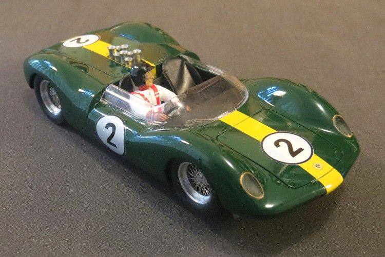
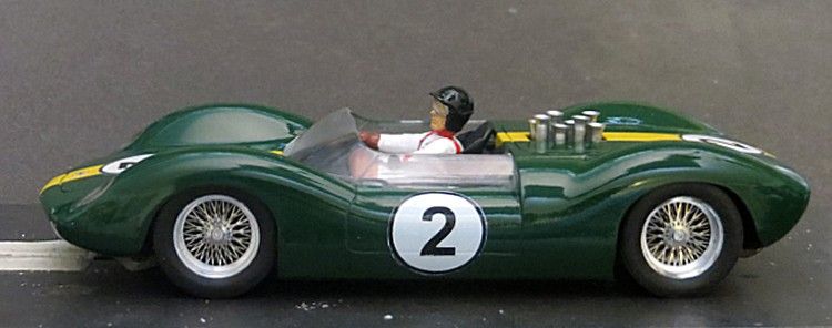
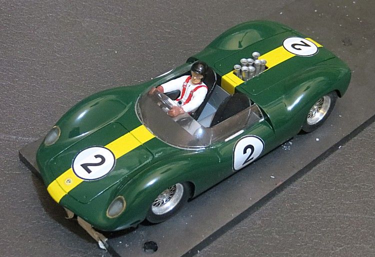
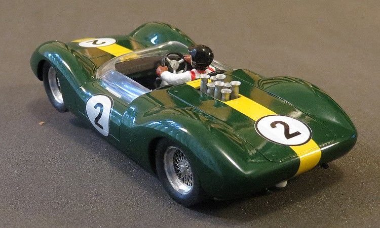
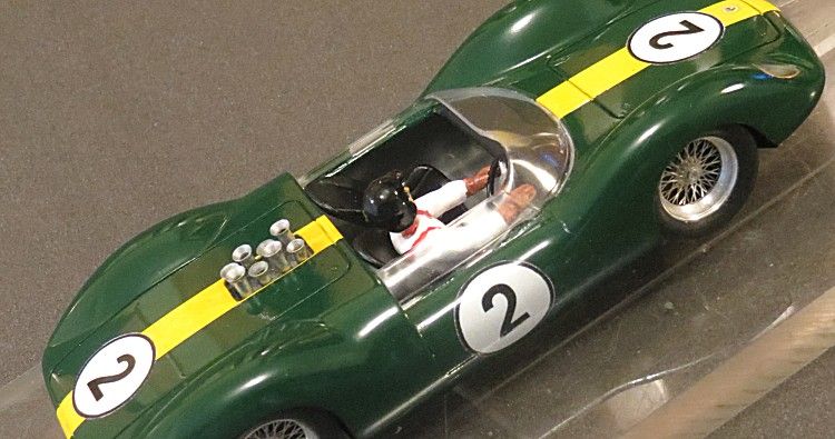
So what did we end up with? I think this is a fabulous model which runs well with the little HO motor valiantly churning away. A serious challenge to an NC1 and even more fun with similar models. As mentioned before it isn’t strictly detail correct, but there won’t be many onlookers who could tell, so is that important? What is important is that it fulfils its roll as a slotcar which to me is to look good and to drive well, and this model does both! I have given myself 9½ out of ten!
I would like to thank friend and fellow slotracer John (the Eggmeister) Van Egmond for gifting me the body, and fellow slot builder Ted (Deslotted) Ayers (WA) for gifting me the wheels and tyres and both refusing to take payment for either).