


.
(Another) Auto Union Type D
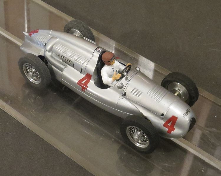
by Phil Wicks
Just when you thought there were no challenges left in slotcar building, someone asks you to put a kit together. Not any ordinary kit either. As slot car racers we tend to race models of anything which has been produced since the 1940’s, and there is now plenty to choose from and no shortage of choice. But for pre war models it is a different ball game. One reason they are not so plentiful is because the mainstream slot and model makers for the last fifty years have avoided the topic. There are a few models made in the fifties and sixties which can be converted but the choice is minimal.
Any pre war body that can be found is usually of poor dimensions and as a slot car would need a lot of alteration just for it to circulate the local slotcar track with any confidence. Models of early racers have flimsy wings (guards) and other parts vulnerable in the inevitable first roll over; and a narrow footprint which negates non magnet racing, which is what we want to do! So for many years the easiest to find models were possibly the worst; Bentleys, Alfas, Aston Martin Ulsters, Bugattis and the like. But there are two or three models lurking amongst these venerable marques which are worth looking for and making a decent racer out of without too much dimensional compromise! Yes, you can access the fabulous George Turner Models (ref the ERA this board) and others, but these can come at a handsome price, and by sifting through eBay you can kit yourself out with equally as pleasing results.
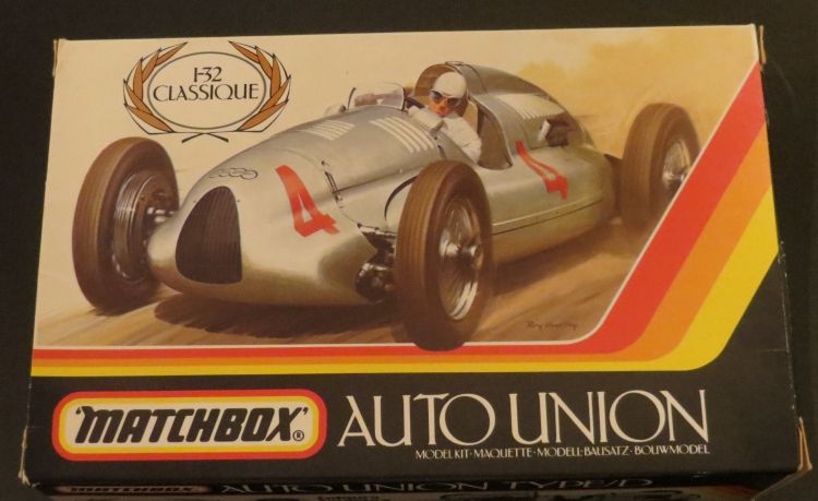
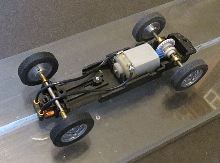
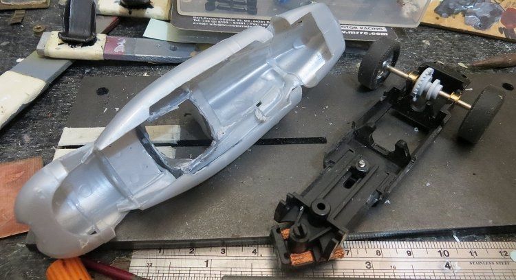
The model I have a soft spot for is the Auto Union type D, In real life a formidable racing car, and on the 1/32 track, the best option for a race winner in your pre war class. So, next up you need to fire up the computer and Google endlessly until not only is the model located, but at a reasonable price too! And it will be worth the bother too! Fortunately, the first task for me was made easy. Good friend and fellow slotcar racer Chris Uttley had the model ready to go, the extra bits required were a driver, a chassis, some wheels and some tyres. The driver was a classic driver as made by MRRC, the wheels were from ‘Peter’s 1/32 wire wheels’ and the chassis a ‘Slot Classic’ chassis which is available universally.
Far from me just telling you where to get the parts, this review is more a simple guide to putting all the bits together to achieve a very presentable, and raceable, model. All the pitfalls and hassles which can be encountered, and hopefully a few novel solutions to help you enhance your model.
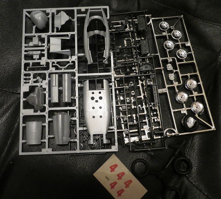
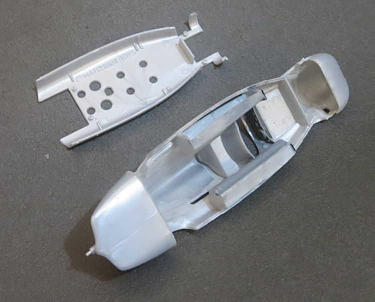
This is not aimed at the master builder, they already have the knowledge, but this model will be just as handy on the track. The first tip is that the model needs to be ready for assembly before the paint goes on. This is a polystyrene body and it won’t take too kindly to manhandling and filing and drilling once it has been assembled, so everything needs to be cut and drilled before gluing goes too far.
First up is fitting the chassis in the body. The chassis comes assembled and apart from the wheels and tyres will go into the body early on. So, following the kit instructions, the body can be progressively glued together. If you have two or three body parts glued, its time to put the model down and do something else. The driver will need painting and there are various other bits to be made. Also, if you want to retain full cockpit detail you will need to ensure the model's driver seat platform is also installed.
This chassis will tuck in under the rear of the body but because there is not a lot of room to spare, the rear of the chassis top is shaped to fit inside the tail panels. The chassis (without the motor and guide) is laid on the underside of the assembled body and the wheel base is adjusted; this is done using the single screw forward of the motor. Once the wheelbase is accurate the chassis outer profile is scored onto the body underside using the tip of a modeler’s knife or even a sharp 2B pencil.
There will be a pair of fuel tanks inside the body; these are needed as they appear as detail in the cockpit. The under body is then cut with a dremel disc, or by other means (a 25 watt soldering iron with a narrow bit is also a good polystyrene cutter). Cut inside the marks and trim to size using modelers knife and small files. Once the opening is achieved and the chassis slides into the body we need to temporarily install the motor and guide in the chassis.
The chassis is then re-presented to the body and further marks made under the nose to allow for the guide to turn, and the rear end of the fuel tanks will need to be trimmed back to allow the motor to fit inside the motor housing. Eventually the chassis will fit comfortably in the body, and standing it on a test block or a piece of track will allow you to make small adjustments to the models stance. Trim inside the body and also the front edges of the chassis until it is level and low. The chassis will need to be trimmed where it fits under the driver’s seat if you want to retain full cockpit detail.
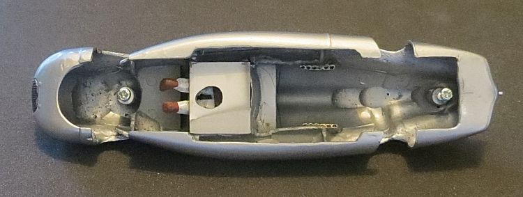
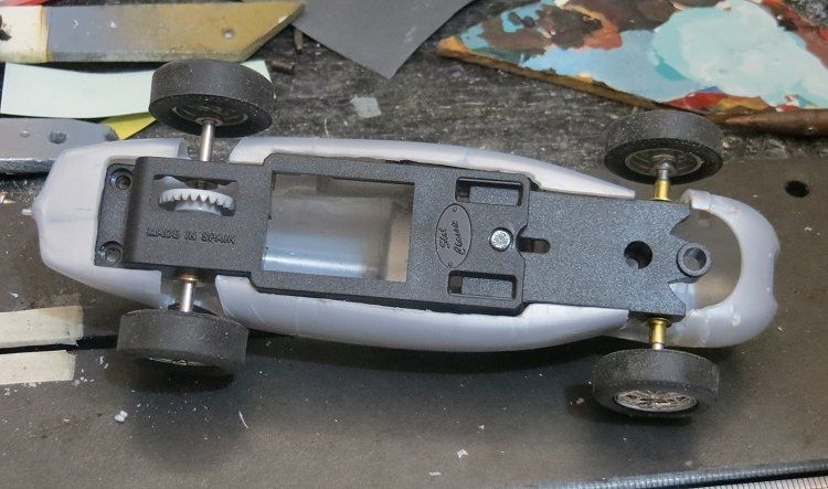
Once the chassis is in an acceptable position we need to create the chassis mounts. We don’t do pins through the side; we don’t do lumps of wood; and we don’t do screws through from the outside to the inside!. What we are going to do here is emulate the definitive mounts that most slotcar manufacturers use. If you are lucky to have some 4 m.m. tubing which takes a body screw then you are very fortunate, in my case I glued two sizes of polystyrene tube together, and once dry, ran a screw down the inside to cut a thread. I decided to use a single screw at each end so the twin rear screw holes in the chassis were abandoned and a new hole drilled in the centre of the rear. The mount tubes where screwed to the top side of the chassis, and after a provisional trim, the chassis was entered back into the body; trimming the posts each time until the chassis sat back in its position.
The post ends were scored with coarse wet and dry and their positions on the underside of the body were scored with the tip of a modeller’s knife. Extra strength epoxy was mixed and applied to the post ends and to the body scores, and the chassis and body were placed together. The posts were applied with glue as it allows the slow curing epoxy to run down the posts and create a larger epoxy bond against the body. The body was then left inverted for twenty four hours.
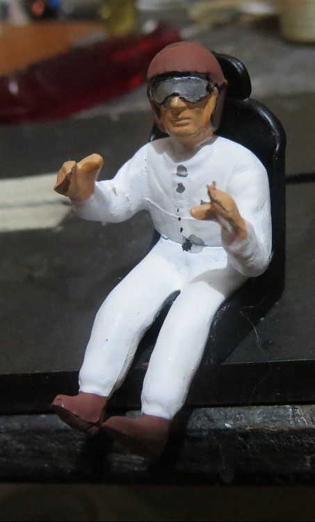
At this stage it was time to determine what we needed to do with the driver!! Sometimes it can be hard to get a driver and a seat and a steering wheel in, in one go, so a plan was hatched to make this as painless as possible. The plan was to glue the driver to his seat, and the wheel to the driver, and fit all the assembled bits in one go! The bits were gathered together unpainted to ensure this was going to go; once happy the driver, wheel and driver’s seat were all painted.
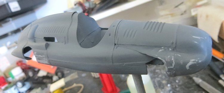
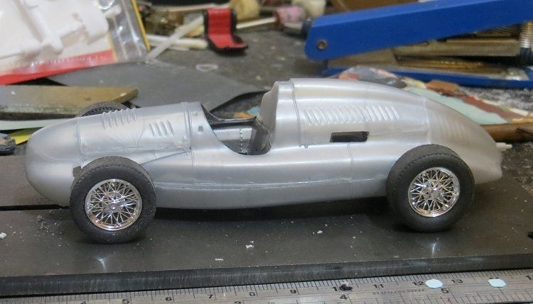
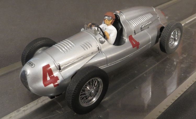
The model has dash detail and although I didn’t spend ages on this difficult to see feature, I did decide to give it a semblance of reality, and , to do this I needed to paint it in after the body paint job. The body had its first coat of flat grey and after drying overnight the body blemishes and poor glued joints were repaired. The repaired areas were then blown over again with the spray gun and again left to dry. Once happy with the primer coat I rubbed it down quite heavily with a cotton cloth torn from an old bed sheet. This acts like a fine sand paper and doesn’t take the finish back to bare plastic. The body was now ready for its colour coat. The real car would have had polished aluminium panels as Auto Union considered there was merit in the weight saving of racing a car with no paint! It has been hard to obtain a true silver finish for a model. Most silver and chrome paints are not convincing and are much too ‘grainy’ for my liking. I eventually came across the solution by accident. One of my past jobs required the silvering of trailer light unit reflectors.
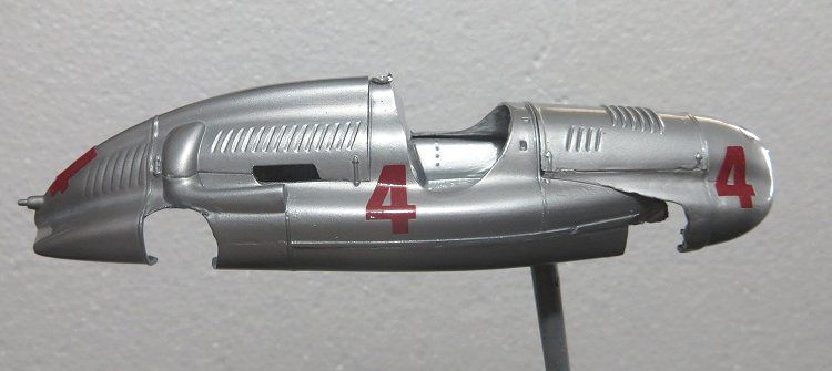
Paint of choice was Septone’s ‘bright chrome’, (available from all good auto stores)! So this was to be the polished aluminium finish I was looking for. The only variance was that as the 400 gram can tends to chuck the paint out in large quantities, I decided to decant a small quantity into my spray gun pot and apply controllably from there! Once dried, I applied the first coat of clear enamel. This time, to avoid contamination as I have had before, the Tamiya enamel clear coat was applied from the spray can it came in.
Decals are now applied and this requires some care too. Soaking, sliding and positioning is straight forward, and we all must have done it a hundred times; the difficulty comes when applying another gloss coat over the decals! Spray paints contain three decal irritants, solvent, drying agent and propellant. Any one of these can react with the decal material and cause them to wrinkle to varying degrees. As the model kit (and decals) is fairly old I decided to take a precautionary measure and use a decal fixing agent.
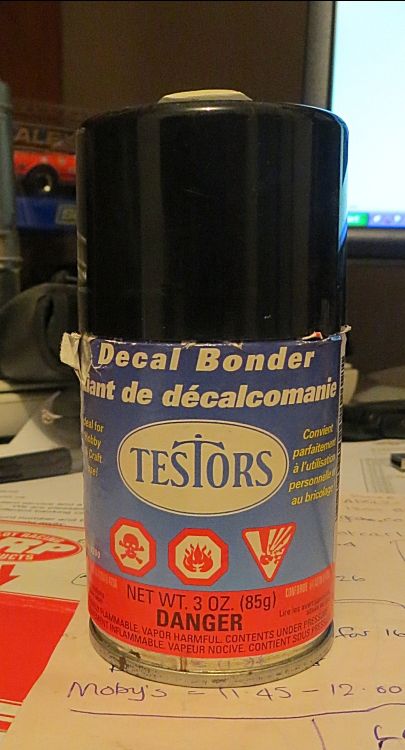
This is used to coat the decal on the sheet, and once dry, it minimises the risk of reaction to spray paints. The product is Testor’s Decal Bonder. It is my understanding that this was developed for applying decals to the inside of clear vacuum formed bodies. Once the body and cockpit are coated the finer detail can be brush painted. On this model there is not too much, and the engine cover strap detail can be painted and the dash detail can have a touch up too.
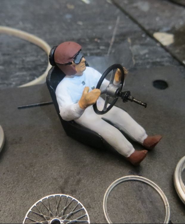
We are now moving into the final stages of assembly. The driver painting had been completed some while back and the driver was now fitted into his seat. The driver will not match the seat contours, that would be expecting too much; so the driver and seat are offered into the cockpit to check the fit. The front edge of the seat was ground away to accommodate the angle in the drivers legs. This was done until the driver’s back was flush with the seat back. The drivers arms had previously been sawn part through and bent and glued to match the diameter of the steering wheel before it was painted., and once the three parts came together, they were dropped into the cockpit where any final adjustment was noted.
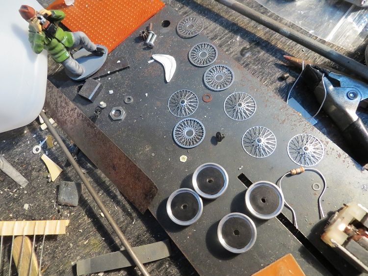
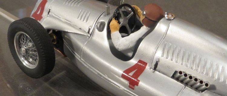
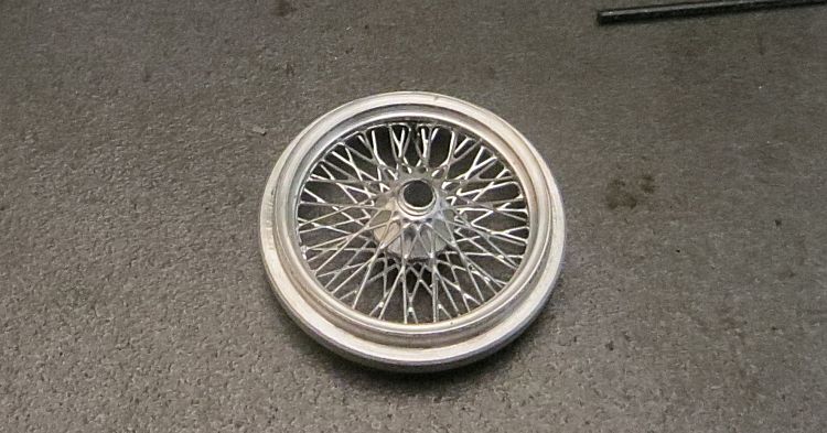
About this time I chose to assemble the wheels. Care also needs to be taken here as there are some small parts which, if you drop them, may be difficult to distinguish from other rubbish on the floor or carpet! Because the spoke detail is discoloured when you get it, I decided to apply a spray coat of thinned ‘bright chrome’ just to make them shine a bit more. It is unlikely that the real spokes were chromed, more likely they were painted the same colour as the body. Wheels are made up of inner hub (with the Allen screw), outer hub (with the tyre fitting step), spacer ring, inner spoke detail, outer spoke detail, conical boss, knock-off ears and knock-off centre pin. NOTE!! THE REAR HUB PARTS ARE WIDER THAN THE FRONT HUB PARTS, SEPARATE THESE INTO THEIR OWN GROUPS BEFORE YOU START ASSEMBLING!
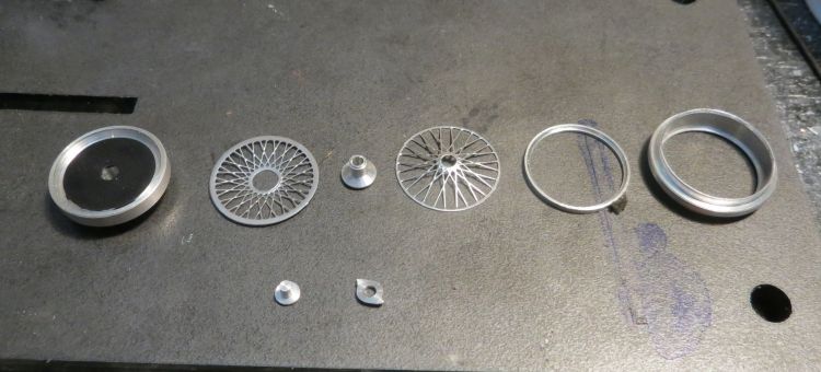
Wheel assembly went as follows; the thin spacer ring is placed in the outer hub with chamfer detail facing out; the outer spoke detail (small centre hole) is placed in the outer hub, painted side out, against the spacer; the conical boss is placed in narrow end first; the inner spoke detail (large centre hole) is then placed in the outer hub and should be sitting on the larger end of the conical boss. The boss is aligned so that it fits in the smaller hole of the outer spokes and the larger hole of the inner spokes.
I then mounted the inner hub on a spare axle and nipped up the grub screw. The next dilemma is what adhesive to use to fix the inner and outer hubs together. Having had traumatic experiences with spokes and superglue and drying times I decided to epoxy the hubs together using long cure superstrength epoxy resin. This gave me room to maneuver! A very fine bead of epoxy was applied to the inner surface of the outer hub using a fine paint brush, a similar bead was applied to the inner hub outer surface. Holding it by the axle, the inner hub was inserted into the outer and both parts were pressed together finger tight.
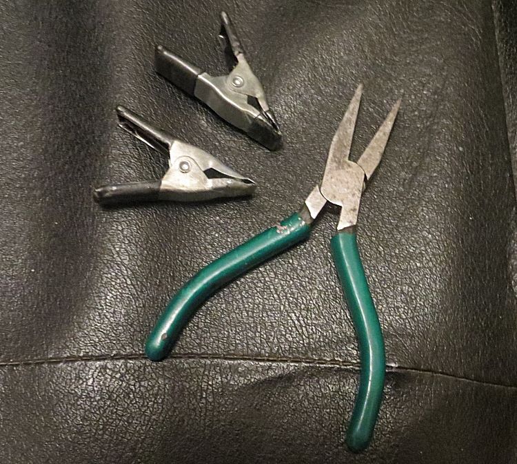
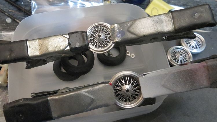
A couple of things to observe here too! Too much glue on the hub parts will see it push through into the spoke detail…..the last thing we want! And it is essential that both hubs are clamped together to remove the risk of ending up with ‘wobbly’ wheels. I have a small pair of flat nosed hobby pliers which I used to clamp the hubs together, doing opposite sides in succession. Once I was happy the hubs were together as far as they would go, I clamped the halves together using some hobby clamps from the tool box (pictured).
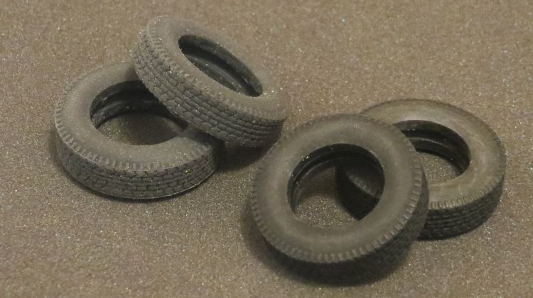
At this time it will be prudent to check that the centre conical boss hasn’t shifted; if it has it can be repositioned using a small drill bit. Once dry (24 hours) the hub nuts can be assembled, and this time I did superglue the nuts to the wheel centres. Final detail here are the tyres, these are urethane remoulds of an Scaley classic tyre and they fit the hubs well. One thing to note is that while all the same size, the front tyres are darker and harder, while the rears are softer and lighter!
The Classic Slot chassis came complete with motor, guide, braids, lead wires and gears, and a set of spoked wheels with tyres. Fitting the new wheels to the axles looked a bit of a doddle but the initial attempt saw one wheel stick fairly tightly to the back axle. Further investigation and measurement showed the axle was slightly bent at one end and the both ends were oversize. I cut a new 3/32†axle from some music wire and carefully bonded the plastic contrate onto it. Both axle bushes were refitted and the two rear wheels were fitted comfortably to the axle and the grub screws tightened (not overtightened!) to the axle. The front axle was a little easier but was still oversize. The front axle comes with some side play inhibitors and rather than making a new axle I turned it in a drill and lightly sanded the ends to size so the wheels slipped on painlessly. Do not force the axles into the hubs, you can easily push the hard won spoke detail out of the other side!
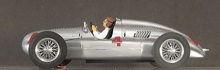
On this model there is a lot of unused engine detail, and the exhausts are part of that. Rather than fiddle pointlessly with the exhausts, I decided to create some new ones with brass tube. Sometime back now I bought a little bag of offcuts from the local hobby store. Amongst them was a selection of small bore tubing. I sorted out several lengths which were going to be candidates for the exhaust, but how to make a neat job of it was the big ask. Having spent some of my working life with jigs, I decided to make a jig which would allow me to make two neat pipe arrays.
Using some left over PCB material I soldered a couple of guides to the surface using six lengths of pipe as a template, I then soldered a stop at one end which would determine the straightness of the row of pipes. With the tube in place and a small piece of brass angle clamped on the tubes to stop them moving, I soldered the pipes together. After trimming to length the tubes were then painted and clear coated. Firstly they were placed through the body slots and lightly superglued in place; I then epoxied them finally into place from the inside.
So we are very close to finishing. The last few jobs are minor detail. The driver was glued to his seat and the steering wheel was glued to his hands! And the whole was glued in place inside the cockpit. I did it this way as there isn’t enough room to get the driver in after the wheel is fitted, or to fit the wheel after the driver! The front grille had a coat of silver and a coat of clear; once dry, I brushed a thinned coat of satin black enamel over it. Once dry the grille was rubbed with some clean cotton cloth to reveal the silver detail of the grille beneath; the grille was then epoxied into its recess.
Lastly was the flyscreen; the model comes with a very nice flyscreen but unfortunately it is thin plastic, so I chose to create one from brass tube and plastic. For the side brackets I filed the side off two short bits of brass tube to reveal the inside. Both the tubes were cut to length and glued into two carefully drilled holes in the body and a previously cut fly screen was trimmed to size and glued into the side brackets. Screen complete!
So there we have it; if this has inspired you to carry out the same task I recommend you have a go, but first you may need to secure the wheels and tyres from Peter at :
Peter's 1/32 wire wheels
The chassis can be your own personal preference but I’m sure the finished article will look great regardless.
All that is left is to hand it back to the owner and see what he thinks of it.
Many thanks to Chris Uttley from Sydney for asking me to build this model for him.