


.
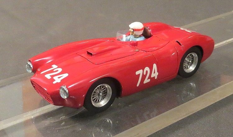
Lancia D24
Resilient Resins scratchbuild
By Phil Wicks
The Lancia (pronounced Lanchia) D24 first took to the road in 1953, and as a dedicated racing car augmented Lancia’s formidable stable of racing cars during the classic years of motor sport. Lancia were to abandon motorsport a couple of years later and their racing stable handed over to Ferrari where Enzo and Co. made good use of the advanced technology which Lancia had developed. During their custodianship, Lancia, with the aid of J.M. Fangio managed to win the Carrera Panamerica and Mille Miglia. Six D24’s were produced of which only two survived. The car had a steel space frame with an aluminium body designed by Pininfarina. Most importantly, the 197 kW of power was provided by a Lancia 3,248 c.c. twincam V6.
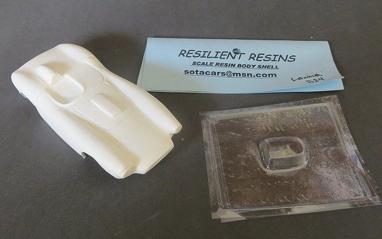
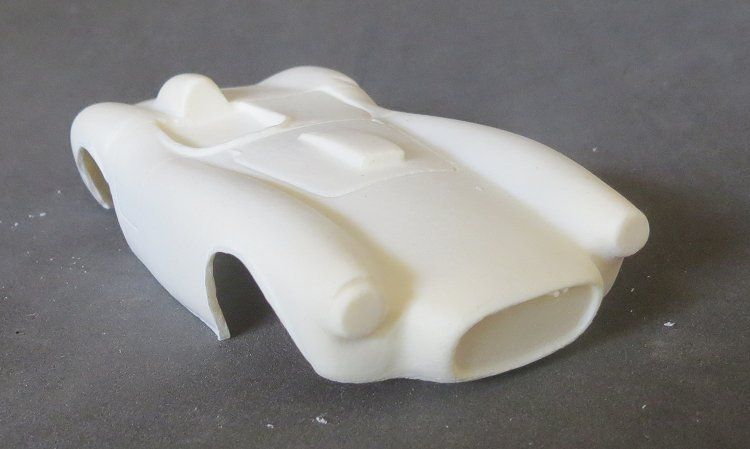
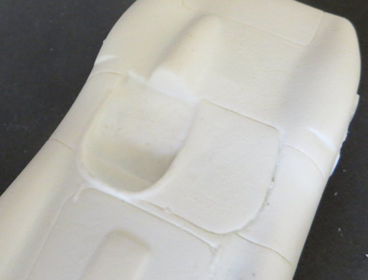
The kit used was acquired one afternoon at a slot meeting at a very generous price (cheers John) and has been in the ‘queue’ of projects for a little while now. The model was made by Resilient Resins in the US. Unfortunately they are no longer readily available due to the untimely demise of the body maker. But, from time to time, the odd example comes up on eBay. The body is a kind of resin but isn’t one of those thick unwieldy slip-cast or moulded bodies. Out of the packet the body is about twenty four grams in its raw state. Not completely perfect, there is still a little bit of work to do on the body, but, the body is the easier part of the conversion.
For the regular visitors here you will remember I have already built the RR Ferrari TR59 (the one with steering) elsewhere in the scratchbuild section. One of that car’s body issues was also present on this model, but we’ll look at that later.
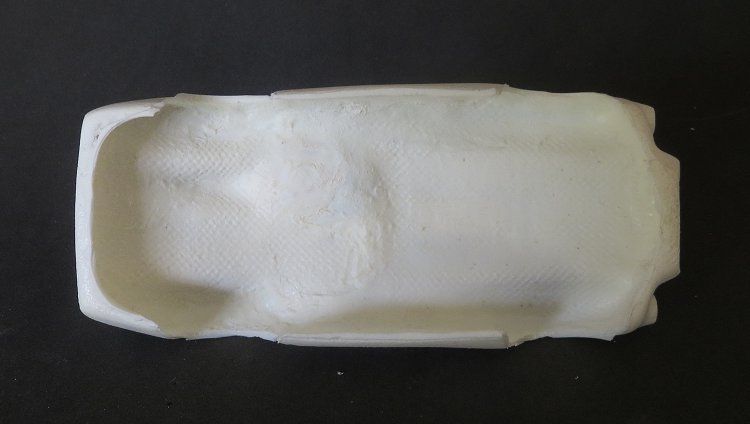
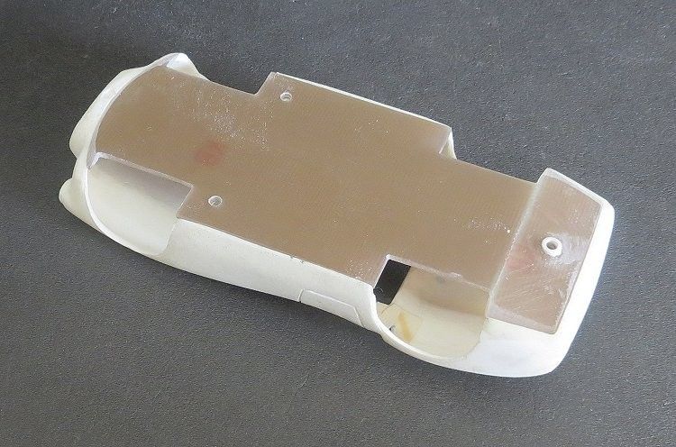
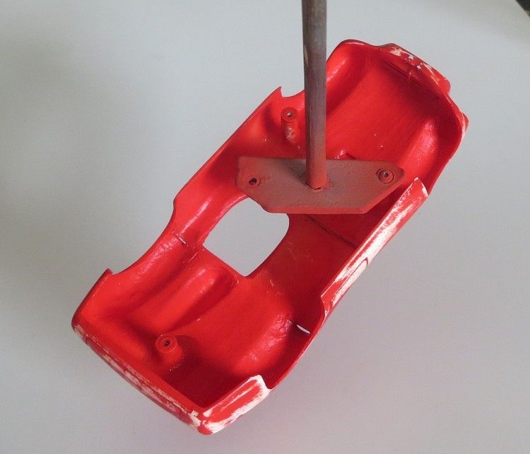
I did go over the inside of the body with the dremel just to get rid of the excess weight in the front and rear of the model. This weight will be added back at a later date, but in more useful spots to improve the model’s balance. The sides also needed straightening as they had a discernable bow in them, this would make matching the chassis to it harder.
This topic is meant to be a ‘walkthrough’ of the building process, and a guide to novices and old hands alike. Some things I do you may not agree with, but I have, and I will endeavour to describe all the techniques used to build the model; where you have better ideas, feel free to use them; and don’t forget to share your techniques!
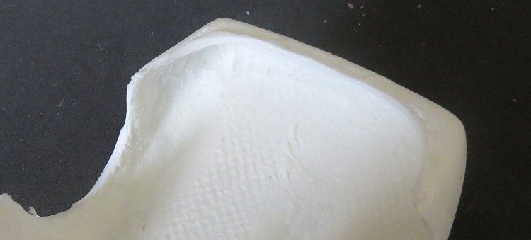
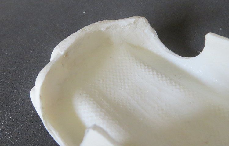
The interior was scraped back using the cutting edge of a curved blade hobby knife. Wheel arches, wells and front and rear valances were tidied up to allow the front and rear edge of the chassis to sit neatly in the body.
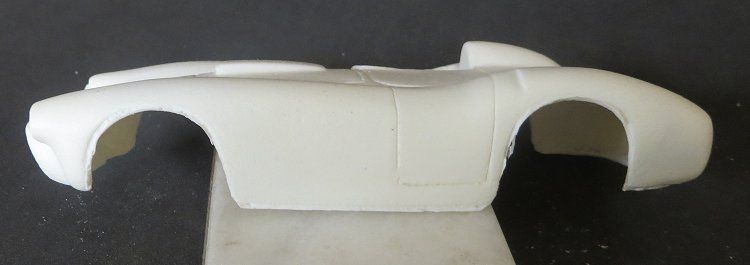
On the outside there are moulding marks which mark the edges of the body. Wheel arches were tidied up a little but final wheel arch work is left until the chassis has been built, this will determine exactly where the wheels will sit in relation to the body.
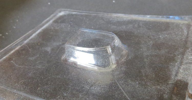
There is a vacuum formed screen, and the screen has a lower flange which will want trimming before it is fitted inside the drivers cockpit hole. The screen height will need to be trimmed once its final position and height is decided.
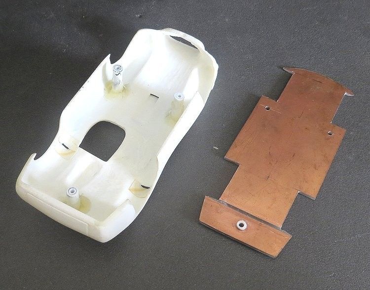
The chassis is marked out on PCB sheeting and a centerline is scored into the copper at this stage. The centre line is very important as it will determine the position of the rest of the components being fixed to it. The first job here is to get it to sit in the body. The inner edges of the chassis sides will need trimming in places, and the wheel wells will need marking out. The first issue is that this is a copy of a hand built model and as such, there are a lot of minor discrepancies in dimensions; the first being that the wheel arches are not aligned side to side, and around the model. Wheel arch positions need to be established and the chassis wheel wells should then be marked and cut in the PCB. The wheel wells should be minimum depth and should just allow the wheels and tyres to sit inside the body line, especially at the front where there are axle mounts and a guide mount to create!
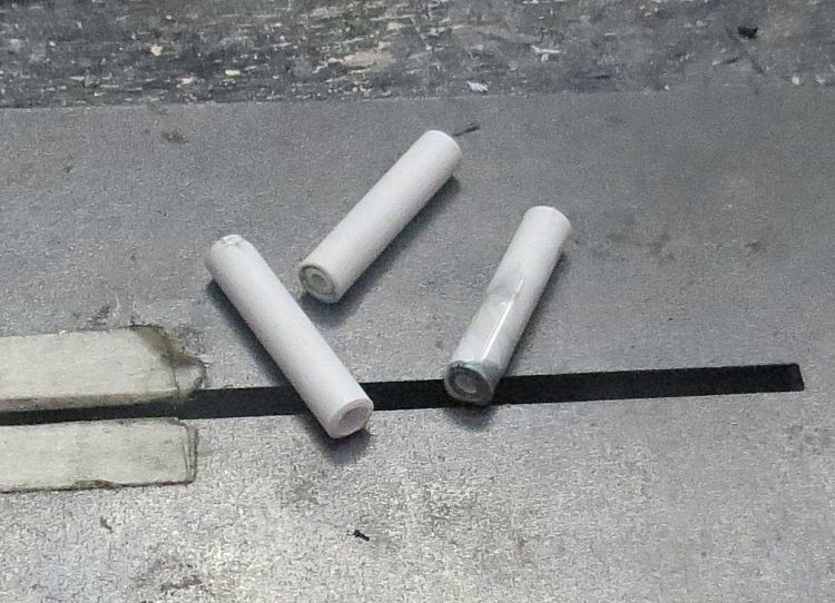
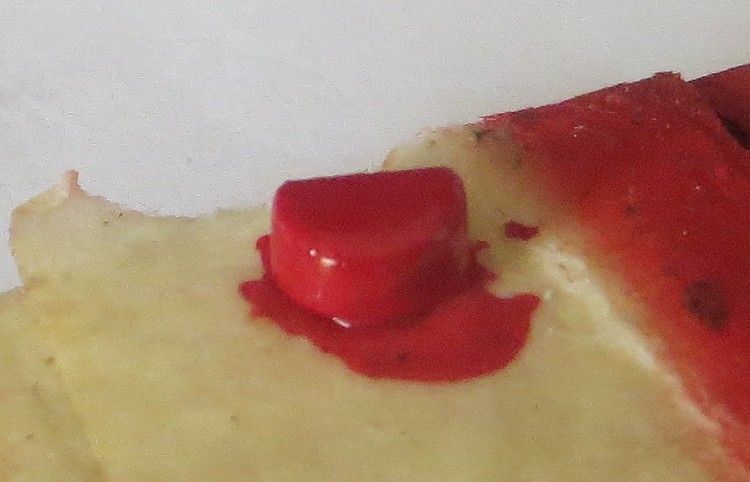
The body mounting posts are made by telescoping two diameters of poly tubing together and sealing them with polystyrene solvent. Allow 24 hours to dry as the tube will be soft for at least this period. The tubes are then put in a small drill chuck avoiding over tightening. As the mounts are turned at low speed, one end of the tubes can be trued by lightly scraping the ends of the revolving tubes with the cutting edge of a modeler’s knife. The trued end is attached to the chassis using the screws to be used as the chassis fixing screws. The tube lengths are then trimmed bit by bit until the chassis sits in the inverted body in the designated position.
The tube contact spots on the body are then marked and scored to improve the epoxy’s keying capability. The upper post ends can also be lightly scored with some coarse wet and dry for the same reason.
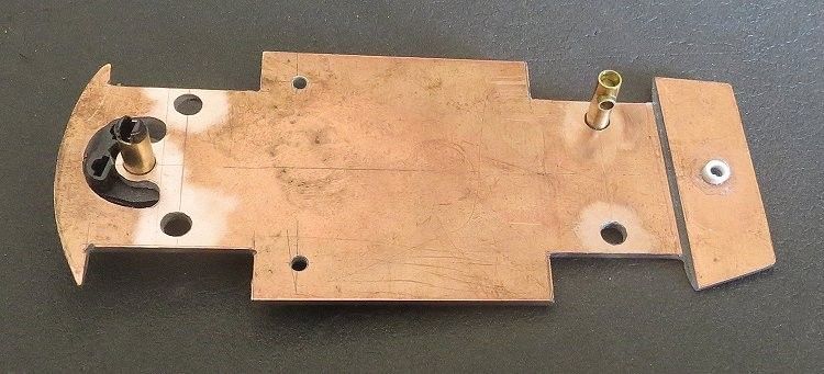
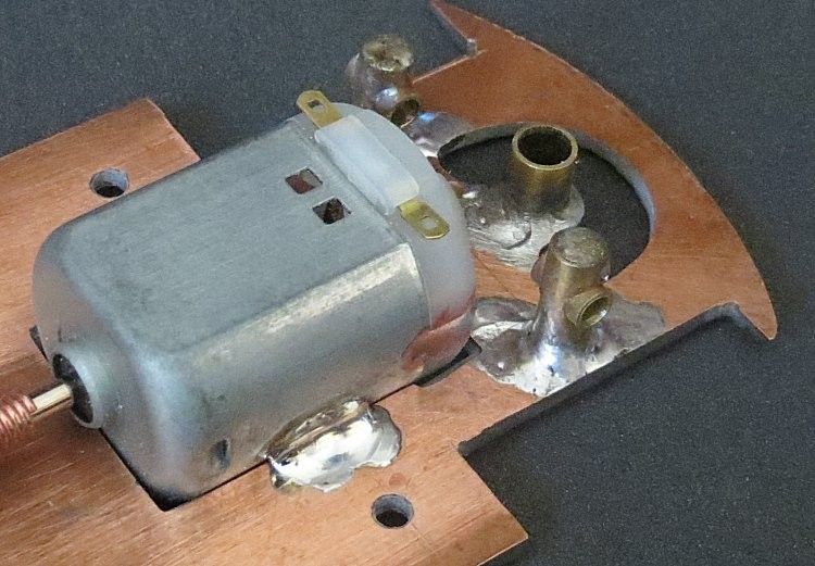
Once the chassis position in the body has been determined, the axle mounts can be cut and positioned. This needs to be fairly accurate as the will determine where the wheels sit inside the wheel arches, but don’t panic, there is room for adjustment before finally spot soldering them in position. The axle mounts are made up of two sizes of brass tube. 1/8 o.d. and 5/32 o.d.. One size should be a snug fit in the other. The bigger diameter is cross drilled to 1/8â€, and the smaller diameter is inserted through the larger diameter create the axle journal (see photos). The guide position can be marked and cut out. In this case I drilled out the waste with an undersized drill and finish of the guide hole shape with a dremel type tool and finally some small modelers files. the guide tube is 3/16" o.d.
You’ll notice I have canted the rear of the chassis up a little to allow the back of the chassis to sit up inside the body. This was achieved by cutting through the PCB with a cutting disc in the dremel tool. The board was cut three quarters of the way through and then carefully bent up to the correct angle. Once the angle was determined, the board was clamped to a flat surface and the board packed up to the required angle. The slot was then filled with superglue, applied over several days until the slot was filled. To get the rear body screw hole in the right position and at the right angle I cut some very thin poly tubing at an angle on one end and superglued the results either side of the screw hole. Once they were dried I filed down the tubing until it was the right height and thickness.
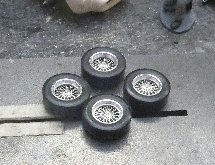
Wheels are 15†classic spokes from Pendleslot (UK) and are a good likeness to wire wheels of the time; the tyres are the excellent MJK (Au) urethane tyres.
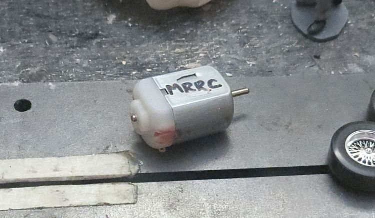
Local rules decided the motor was to be an NC1 as this is the most common class motor for this model. But, Ninco NC1’s are rare so, after some on line research, I discovered that MRRC sold a motor which was a direct replacement for the trusty NC1, down to the last rpm, (unlike a lot of higher speed pretenders on the market). But since buying a batch of these, I notice they have been removed from the MRRC website, and Pendle’s have sold out and discontinued them! More research has shown the Cartrix TX1 to be another NC1 clone and subsequent local testing has confirmed this. A source of these replacement motors has been located in Spain!
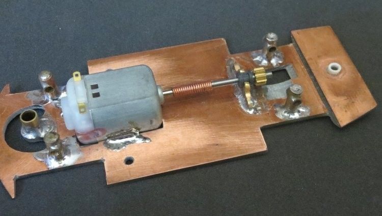
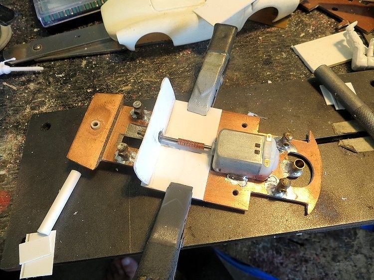
Next up was the power unit position, this was to be a front motor as I wanted to finish the model with full cockpit detail, and there is plenty of space in the model for this. The drive spring was purchases on the internet more than a couple of years ago while I was scratch building some other classis slotcars. The shaft is from a Flycar which had been converted to rear motor drive by a friend some while ago (thanks Paul).
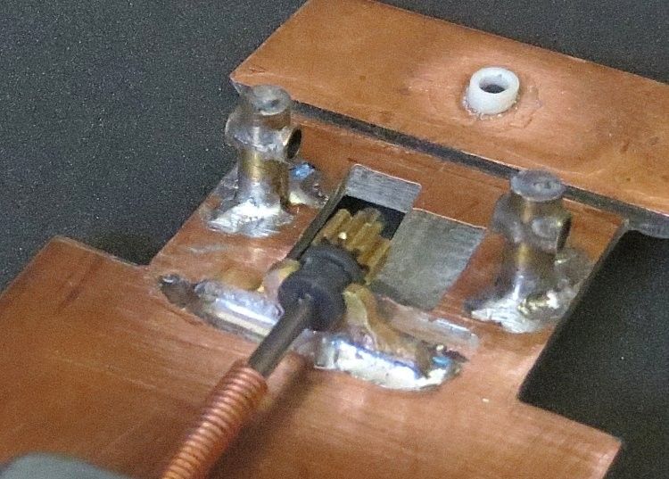
The plastic shaft bearing was also Fly and the bracket was fabricated very carefully from some flat hobby brass. By this stage the axle mounts had been made and installed and the ride height of the model had been established. The axle mounts where then soldered into place.
Note, all the components at the front end can be soldered in place. The guide mount will be the last item fixed in place. The tube is mounted over the guide and with braids and wheels installed, the model is stood on the setup block and the guide is raised and lowered until it sits the exact right height to ensure the guide has maximum slot penetration without lifting the front wheels off the track. A note here, the plastic guide will need removing from the tube before soldering the tube in place……for obvious reasons!
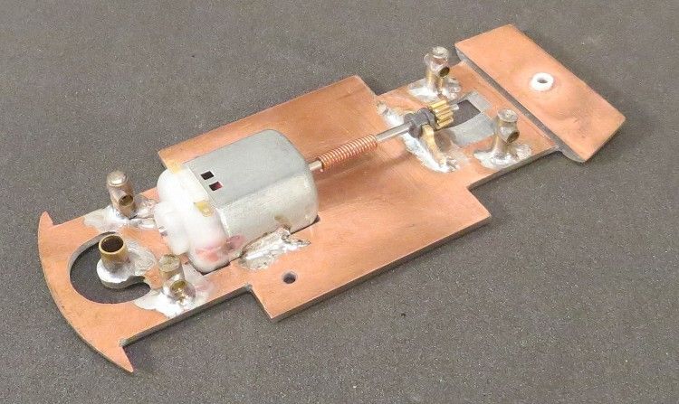
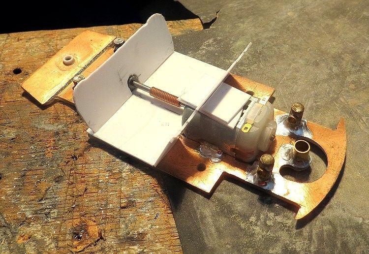
This is what you should finish up with. Once complete, the chassis can be set aside while the body gets all the attention.
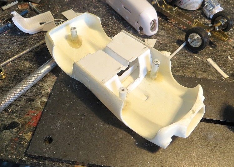
Having a full interior has its own issues. I prefer the option of building the cockpit as a separate item, Why? Because I can get it to fit the body properly, and I can get it to fit the chassis well too… This has to be done to ensure the chassis fits into the body once the cockpit is fixed in place. It involves a lot of ‘offering up’ and altering, but is well worth the end result.
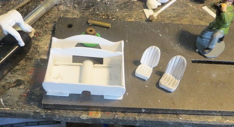
Starting point is what I call the ‘saddle’, once this fits both the chassis and body, the rest is a doddle! Trust me. The end pieces are offered loose into the body and shaped to fit the inner body shell, the bottom edge is then shortened to allow the chassis to sit home in the body, a third piece of flat pastic is placed in tas the floor and with the body screwed in place, the three pieces are glued together; things then get easier!.
What’s this??..... well actually, it is a (laminated) seat base, I didn't have a piece of plastic thick enough. The underside of the base will later be sanded at an angle to allow the seat to be posed in a reclining position! It will be profiled and shaped to fit the cockpit space available, and to fit in with things like the transmission tunnel, steering wheel, driver etc.
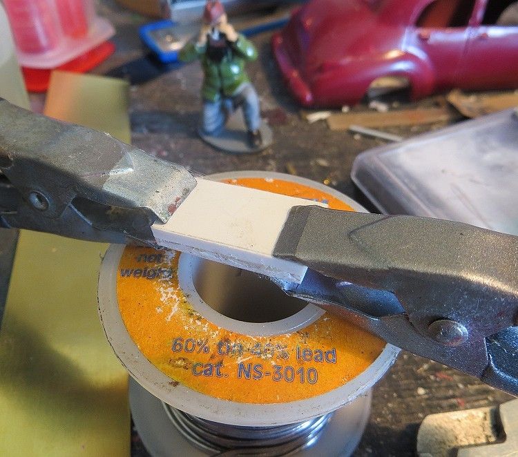
The transmission tunnel is made from plastic tube; the tube is cut to length then split lengthwise. Using some flat pliers the side edges of the tube is flattened until the desired profile is achieved. Seats have been matched to the driver’s dimensions. Another ‘dimension’ which is suspect is the hole in the body for the cockpit. When the car was modeled, the hole was made too close to the body centre line, and as a result seats and driver had to be modified to accommodate the problem. I could have rectified this in the early stage by widening the hole, but was unaware of it until well into construction. But moving the hole over would then have required a new screen!! You can’t win some days!
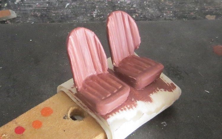
Seat backs were laminated (‘several thickness’) so that the material could be bent (see the Lotus 30 build). The laminates were glued together and the curved seatbacks were held in a former for a coupe of days until the glue had dried completely. The seat cover ribbing was added by scoring with the point of a modeler’s knife.
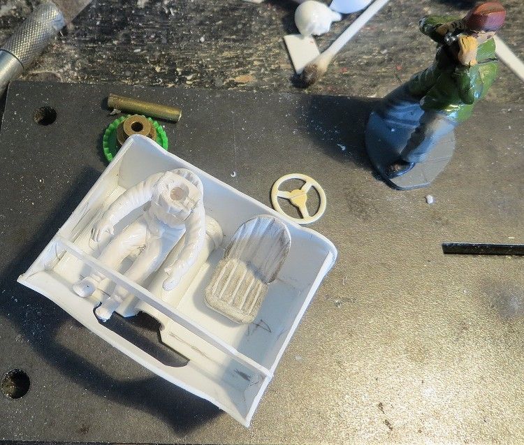
All bits are offered together before painting; this is essential! I made the steering wheel too, this is a one piece hand carving and I had to make it smaller than it would have been because there was no space left in the cockpit for a life size steering wheel. The wheel eventually gets a steering shaft which passes through holes in the saddle and the dash (the brace across the front of the driver is for the dashboard). Notice the second seat! Not visible in the model, but I know its there!.......
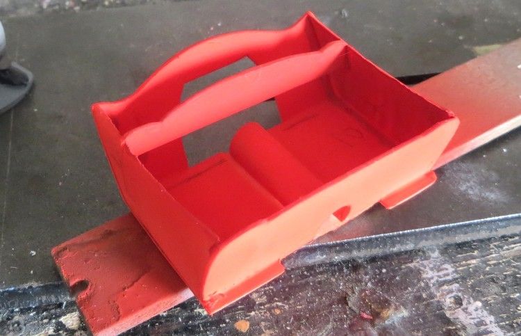
As always, check, check and check again. This is the driver’s tray in place making sure it clears the body posts and fits the opening in the top side of the body.
Tamiya flat red acrylic is a good undercoat/filler for the enamel top coating it will be getting. The enamel coat doesn’t affect the acrylic at all. Other parts like the floor can be brush painted.
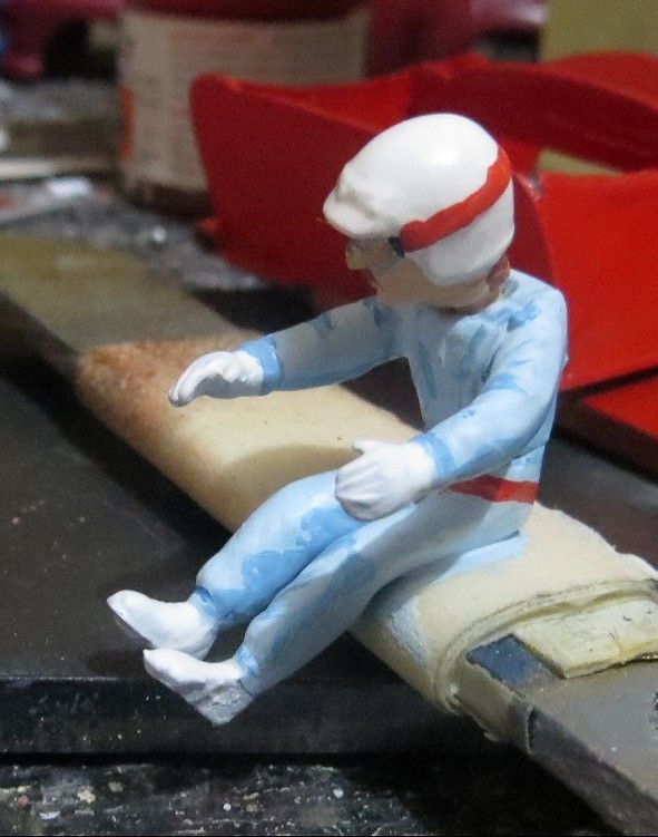
The driver gets his fair share of treatment too. The body has had its arms broken, lowered and widened more than once to make them fit the cockpit / steering wheel detail. Also, I chose a small body to fit into the cockpit, but chose a larger head to peer above the flyscreen without it looking too small.
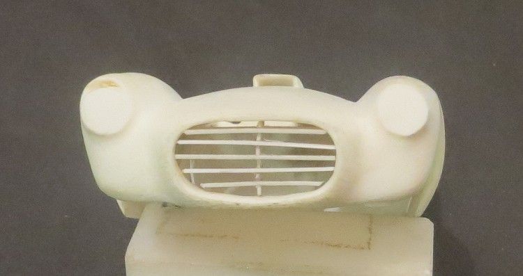
The D24 has an unusual grille at the front end, so rather than shy away from it I made a grille by using thin plastic which interlocked into a centre stay, much like the real thing. The grille bars are shaped and offered into the body front opening.
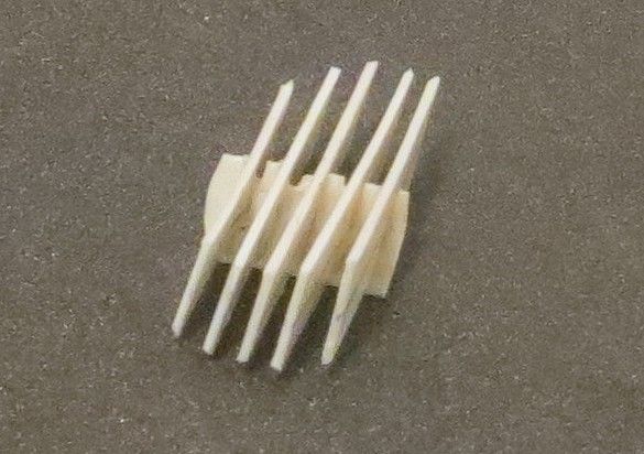
The cross bars are lightly glued into place on the centre stay and once again the bars are trimmed and offered, trimmed and offered.
To avoid getting paint all over my hands, the body is mounted on a lolly stick jig, using one of the body mounting posts and screws.
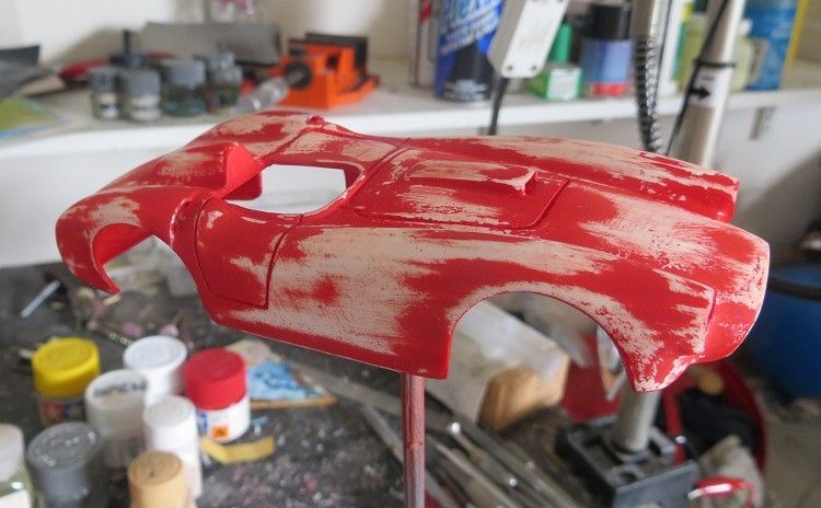
Final rub down and ready for the finishing coats
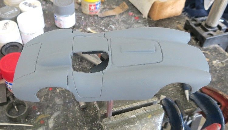
With the filler coat smooth and rubbed back, I applied a medium coat of flat grey acrylic. Body detail was checked and any remaining defects rectified and coated before going further. The final grey was rubbed with some cotton cloth which acted a bit like 1500 wet and dry.
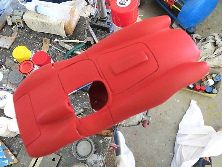
Then a final coat of flat red over the grey coat. The flat red is a fairly translucent colour and the grey under was used to give it more depth and body. The flat red top coat was used to give the gloss enamel top coat more body. This coat was also rubbed down with cotton cloth.

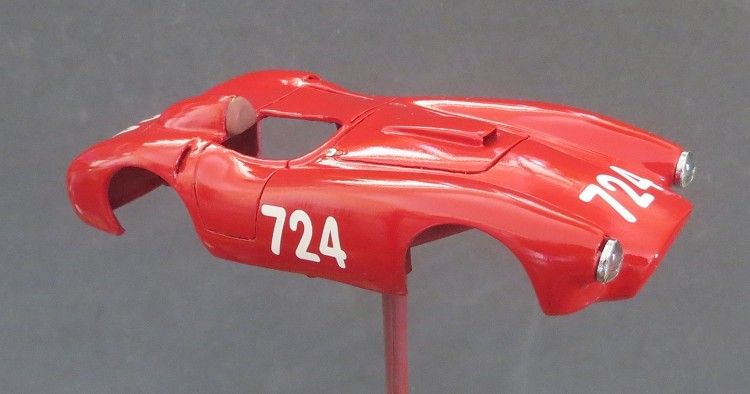
Topcoat applied, gloss red enamel (Tamiya Italian Red), This model will only have one coat of gloss, but it will have three clear coats.
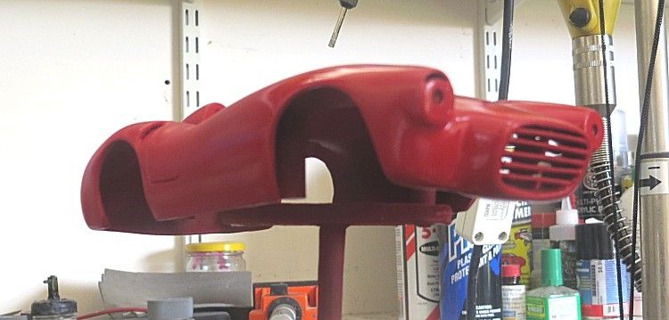
Unfortunately the camera I use (Canon!) doesn’t give reds their true hue, this is one of the few pictures where the colour is almost correct. It may be the way that the camera deals with artificial light on automatic settings?
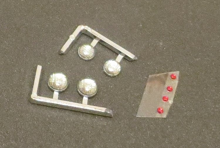
The body does not come with lights so I purchased some 4 and 5 m.m. headlights from Pendleslot not knowing which was the best size. I also bought some tail lights but in hindsight should have got the next size up. The headlights will eventually be shallow bored in their back and their mounting spot will get the same treatment; this will give the full strength epoxy a better chance to key to the body and light material, hopefully giving it some extra ‘on track’ resilience.
After the first coat of clear the bonnet and boot straps, lights and headrest are fitted. The decals are applied (I choose some Mille Miglia numbers for special effect) and after about twenty four hours, a second clear coat was applied. I use Tamiya clear coat enamel straight from the spray can, having had problems in the past with dark specs being emitted from hard to clean spray guns. The spray can is left in a warm bowl of water for ten minutes before spraying commences and is then shaken vigourously for about a minute and a half.
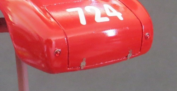
Rear lights and boot straps epoxied in place. The paint is bored carefully with a small drill to allow the epoxy to bond to the body material and not the paint.
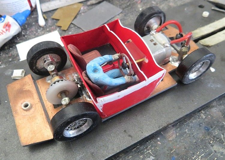
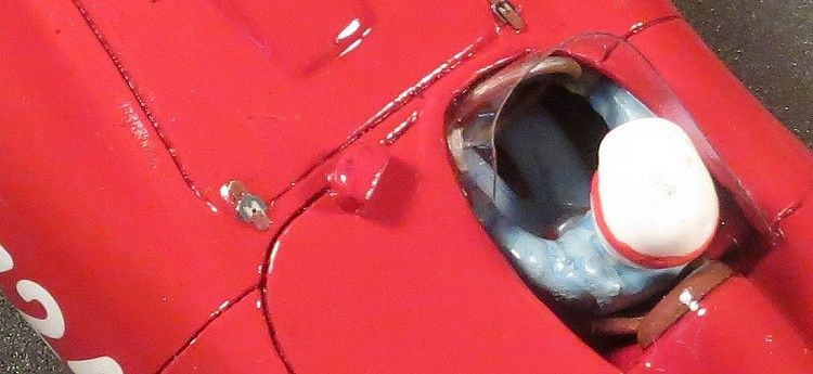
Getting close to completion, the driver’s tray is painted and populated, and a gear lever and handbrake lever are fabricated, even though they will be almost unseeable! The driver’s body and steering wheel go in together. The driver is superglued to his seat by his bum and the steering column, once in situ, is spot glued with superglue where it passes through the tray.

The driver’s head will go on once the tray is glued to the body, this is to make sure it can be posed in conjunction with the headrest. Also, earlier, the end of the motor was painted gloss red, this negated the need to finish off the drivers tray under the dash area. Once dry the tray is offered into the body and the chassis is installed minus its wheels. I used some full strength epoxy to fix the tray into the body. Using a small paintbrush, the tray/body joining areas received a bead of epoxy via the wheel wells. Again twenty four hours later the model was separated and the remaining contact areas got a thin coat of epoxy.
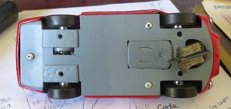
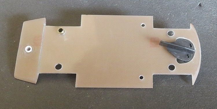
The parts on the chassis underside were masked and after a good clean the chassis underside received a coat of Tamiya ‘neutral grey’ flat paint. Why did I leave it ‘til now? Well, the chassis is handled continuously up until this point and it is difficult to keep clean with so much going on; so I decided to mask and paint the chassis last, make sense? Note, there has been ten grams of thin lead attached under the rear axle (superglue). I have found this to be adequate on other models for this class of motor giving the rear of the model abut five grams more weight than the front. The urethane tyres work well with a light load.
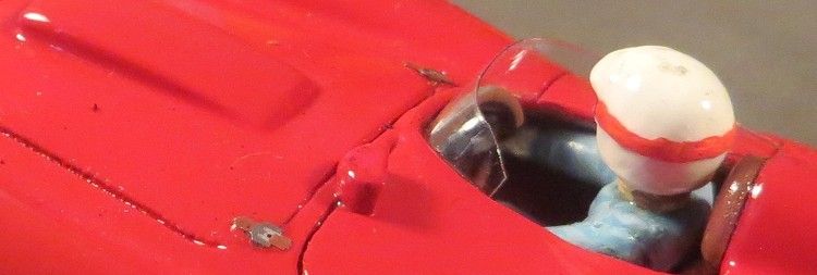
The neck hole in the drivers body had been widened some time before, this allowed me to ‘pose’ the finished drivers head in the cockpit and avoid that stiff look that a lot of RTR models have with one piece drivers.
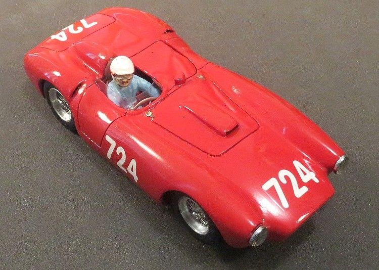
Not visible together at any one time is the discrepancy of dimensions between sides. The maker of this model has done a good job but the left side is definitely different to the right! The wheel arches are two different heights and likewise the wings (guards/fenders) and wheel wells do not share a dimension or align with each other.
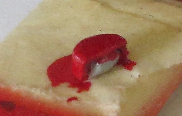
A job I nearly forgot was the rear view mirror. Hoping something might turn up I eventually made the mirror out of plastic sheet and shaped it once the glue was dry. The body of the mirror had the requisite number of coats of paint and clear, and a sliver of ‘Bare-Metal’ foil was applied to the mirror surface. As with the other body fittings, the mirror and its spot on the body were counter bored lightly with a small drill and the appendage fixed in place with a moderate spot of epoxy.
Painting the mirror required it to be stuck to one of my self adhesive holders. The mirror had to be above the surface of the holder or it would have ended up with a paint flange around the base which is not what I wanted to achieve.
Bonnet straps, mirror, screen and drivers head all in their final resting place.
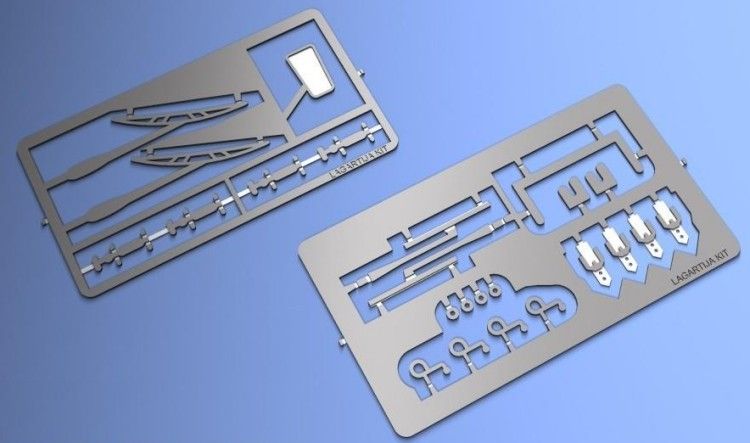
Small parts from Lagartijakit 1/32. Note the bonnet straps on the far right.
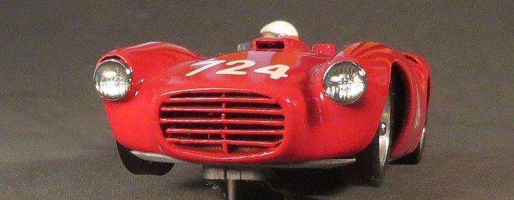
Don’t look too hard but the grille is almost perfect not!!(further lessons to be learnt there!)
Another shot of the small fittings. I decided to shorten the passenger side of the screen as it was common for cars with removable tonneau covers not to have a screen attached to the cover.
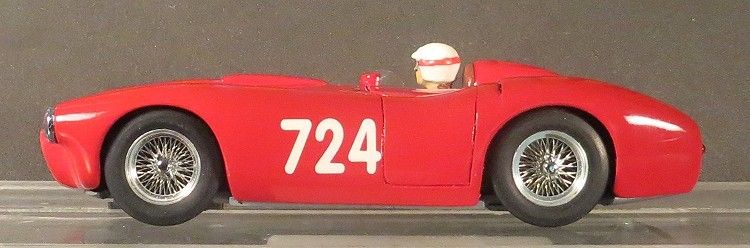
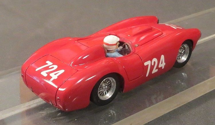
The ‘good’ side of the model. On the other side, the wheels are definitely further into the wheel wells.
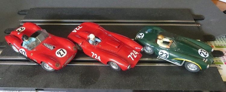
This is the ‘stable' taking shape. To see these cars together is awesome, and if you have a mate or two with similar era cars, so much the better. Next thing is to get them all on the track together!
I hope you have enjoyed this ‘walk through’ as I have done it. I have tried to avoid any bodgey techniques as these are the first things to go wrong or fall off. I have friends who have bought bespoke scratch builds at great cost from the internet only to find that each time they are taken for a run, something more falls off.
I have designed this model to be raced. The chassis layout and its mounts have already won races and the body has been kept simple. The external detail has been well fixed and should endure the rigours of racing. The only thing I cannot duplicate is the bullet proof paintwork of an off the shelf model. The paint will chip, but the use of enamel top and clear coats should give it a degree of ‘bullet proof-ness.
So get onto ebay and type ‘resin body’ into the search engine or click the link below, hopefully this will give you a good choice of models. Enjoy
Resin bodies on eBay