


.
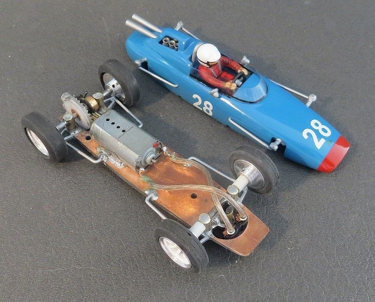
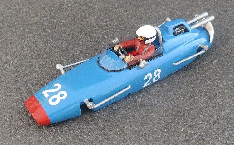
Lindberg LOLA Mk4 GP
Rebuild
by Phil Wicks
I have often looked and wondered how well I would fare by entering a proxy race, I have always been a bit apprehensive of the idea because being a control freak, I would want to be there making sure other people are driving my model as it should be driven. I already belong to a couple of race groups and where as I am quite happy with the results I get with my cars during full on race days, I often wonder how well my cars would go with someone else metaphorically ‘at the wheel’
I am guilty in that I do not let others race my first string cars, especially my scratchbuilds, and if someone gets in a spot and needs a model, I usually give them a good model, but still an ‘also ran’ unless I am completely happy that they will bring it back in one piece.
I also pride myself on being a careful driver who is not hard on a model, and one who usually can complete four or six heat with very few, if any, deslots. The logic being that if I am deslotting, I am loosing ground; and if I am deslotting one of my precious scratch builds I could quite easily be damaging a very tidy paint job which would gall me even more!
So, back to proxy racing and classic GP in particular; and the trick is to formulate a plan of attack, not only for the model build, but for multi driver syndrome. What’s needed for this is comprehensive information regarding the tracks, the power supplies, the controllers and ideally….the drivers! These will vary from leg to leg, so a good knowledge of each venue is needed to build an ‘all rounder’ which will do well on ALL surfaces.
After all, there is no point in winning on a gloss painted, copper taped conductor track when you will bomb badly on a four lane Ninco (or vice versa)! What is needed is a good all rounder so your race average is high; four seconds is better than three firsts and a DNF!
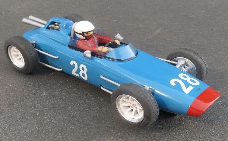
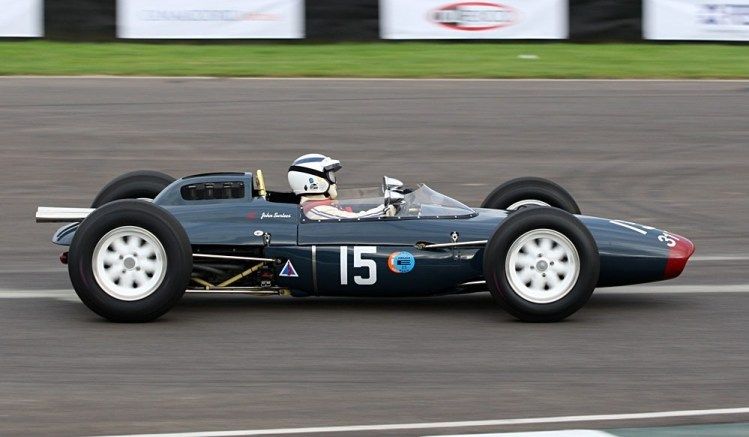
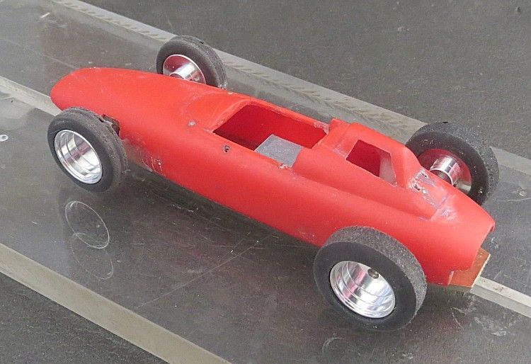
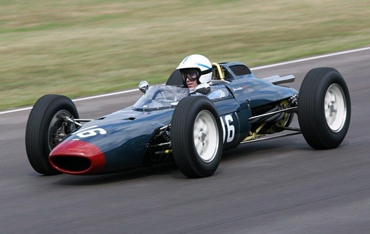
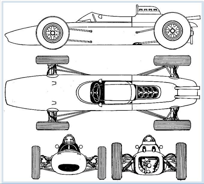
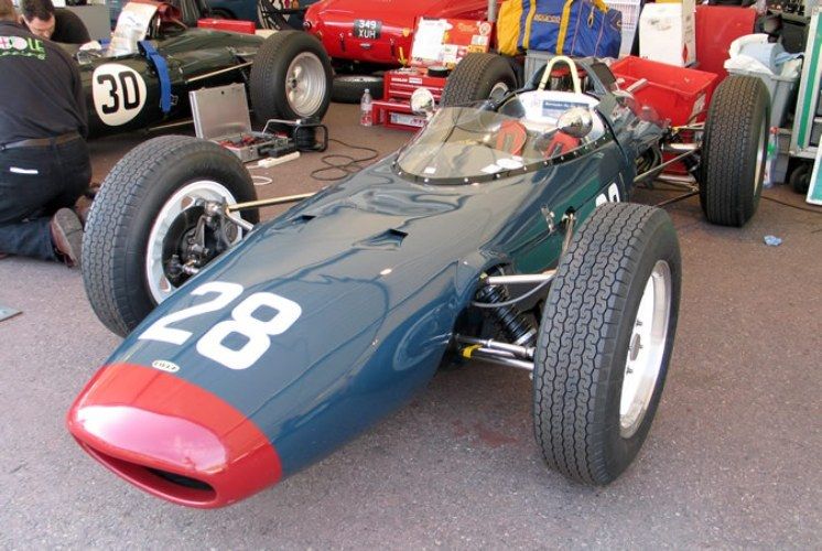
The model I chose to build has broken my first golden rule; which is, pick a model to suit the event, i.e. a low down model with low C of G, wide track and a short tail and wide tires. The body I have chosen is a sixties Lola MK4 as made by the Lindberg company, and where as it is moderately accurate scale, it was designed to take a clunky open framed motor and therefore is a bit bulbous about the midriff but no matter, I have specialized in the past in getting pigs to fly and I’m sure this one will present no greater challenge
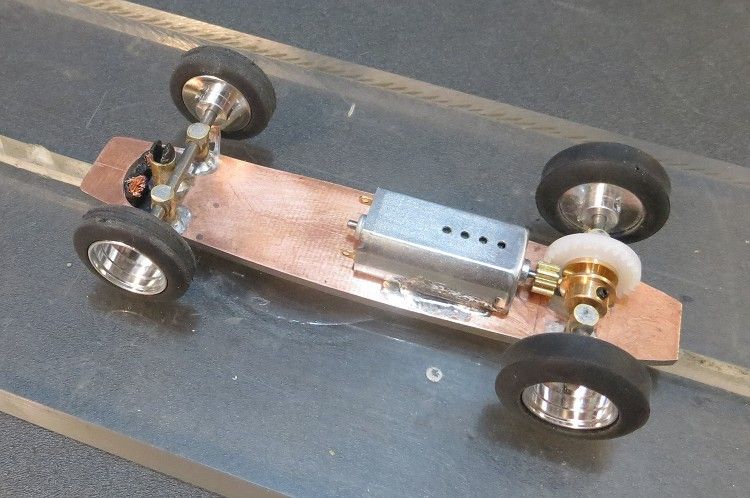
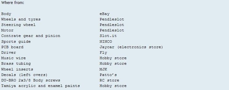
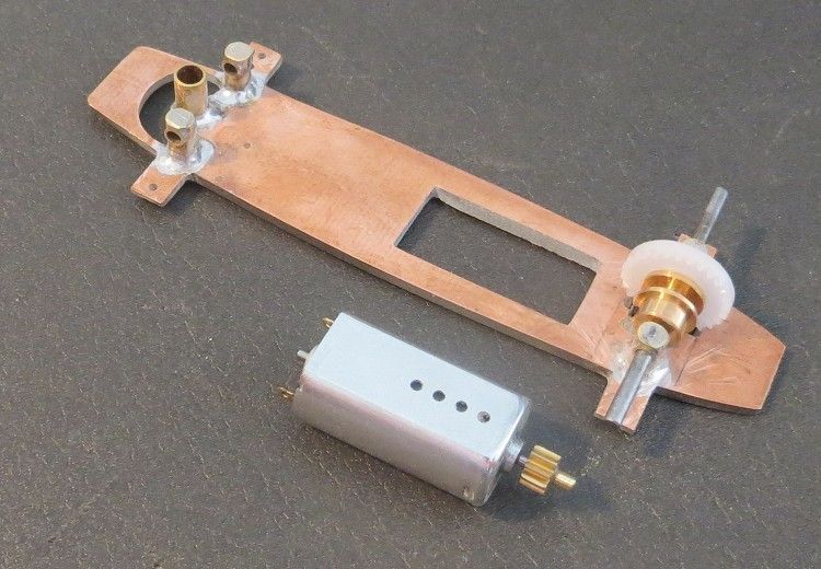
First up was to decide what features it would encompass, My trademark circuit board chassis was always the first option and it would be powered by a 16,000 rpm slimline FF type motor. Gear ratio was to be 3.0:1 and wheels and tyres would be off the shelf from Pendle’s. Slot.It supplied the pinion and contrate and the axles where made from 3/32 music (piano) wire from the local hobby store.
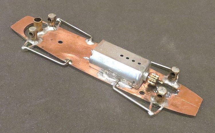
The chassis needed to have a little more detail than I would normally bother with as it is usually part of the proxy car spec, so external suspension detail was required in minimal quantity; for me this was to be tie bars attached to mock wishbones’ control arms. The thing is it can become very complex (and frustrating) to create this all from bare wire.
Jigs are required and soldering skills need to be well up to scratch, with the glass resin circuit board I would incorporate some of the detail to the chassis and the remaining upper and lower tie rods would be fixed to the body and chassis respectively, so simple additions to the chassis and body design will take care of the anchorage spots.
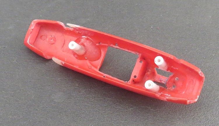
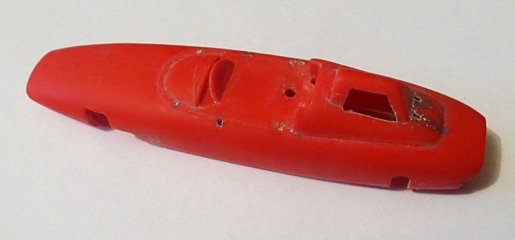
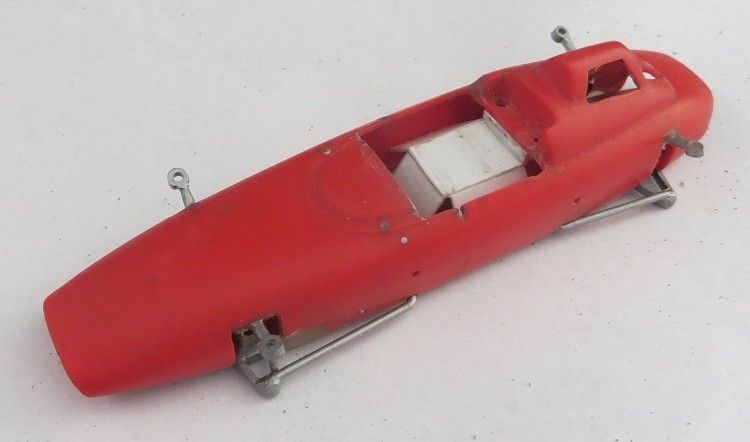
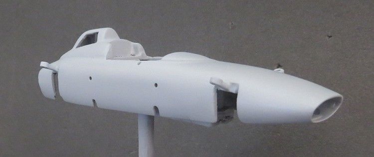
The body is next for some preliminary ground work. The chassis will be tailored to the body but firstly the body needs to be cleaned and tidied in anticipation of the chassis. The Lola is an old scrapyard item from a friend’s eBay lot so it came complete with daggie paintwork and various nicks and dents, plus there were areas where missing body panels needed to be created.
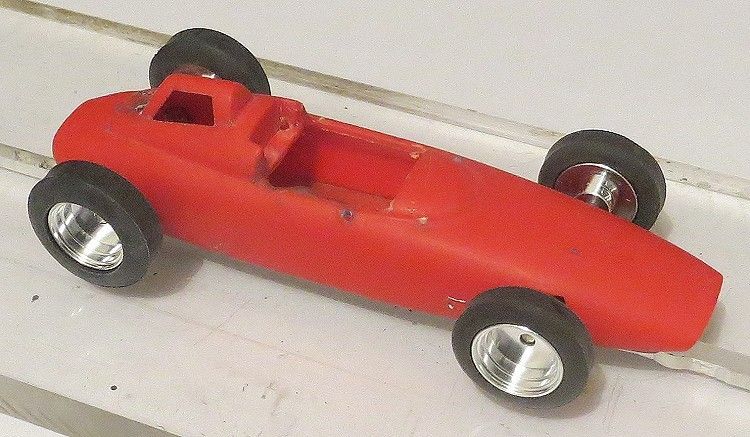
Once tidied up the missing bits were cast direct on to the body. This body shell had a section of rear skirt missing on the off side, and there were cut outs where what looks to be a steering unit must have fitted. I was running a solid front axle (this time) so, the non scale cut outs on the front axle recess needed filling.
A couple of thin squares of polystyrene card were cut to shape and superglued to the inside of the body these projected across the missing body area. Some extra strength epoxy was mixed and applied to the area. After about twenty four hours the card was pulled off and the epoxy was left another twenty four hours before the filled areas were sanded back into shape. A second application was needed to fill a couple of low spots and likewise would be rubbed back. Once complete, attention was switched to the chassis.
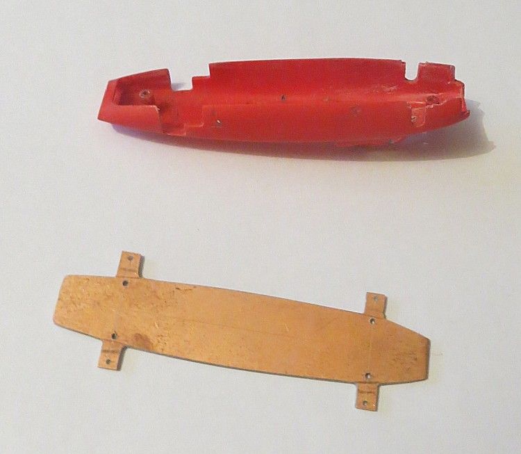
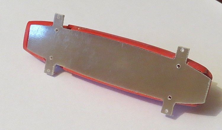
The body opening dimensions were taken and transferred roughly to the copper side of the board; I actually placed the body on the board and drew around it with a pencil, this gave me a chassis which was oversize by probably the thickness of the body. Once arrived at, I measured out and marked a centerline from front to rear, this has to be pretty accurate as this is the line all other dimensions are taken from. And once the axle width is known, the axle positions are marked, also on the copper side.
The suspension detail position was marked on the chassis and other important dimensions such as the axle mounts, the guide hole and the motor cut out. Once happy with these the shape of the body was worked around these dimensions. A combination of hand files and dremel were used to get the chassis down to its final shape. I must admit, because there is not a straight line on the body shape, I spent several hours getting the chassis, by trial and error, to fit the underside of the body. Once happy with the fit, I measured and marked the suspension detail to the board, this was to be mock wishbones. The waste was drilled out and the final shapes hand filed into the correct size.
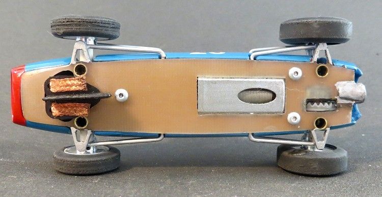
I have documented the creation of this type of chassis many times before so I will not labour on it. The chassis needs to be marked out very carefully as there is not a lot of space to spare, and being a resin based chassis, if you cut it wrong it becomes scrap, no resoldering of parts here! The axle mounts were made from intersecting brass tube and the guide mount was similar. Axles were set up with wheels and tyres in their final dimensions and once happy with the model’s ride height on the set up block, the mounts were spot soldered in place. The protruding tubes on the underside where trimmed back flush with the underside of the chassis.
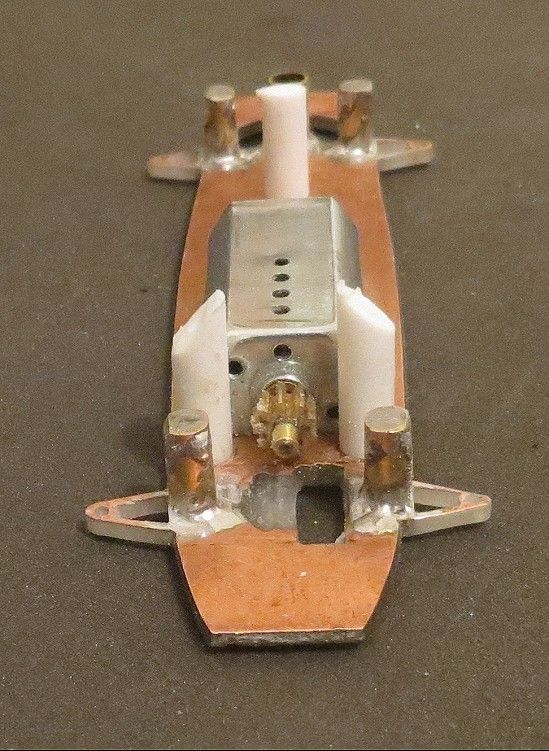
Next up was fixing the body to the chassis, this was achieved with the ‘Wixwacing’ patent body mounting posts; again, many topics in the scratchbuild section will show you the best way to do them. I chose three posts for this model as I wasn’t anticipating running it with a loose body and the third screw would help the body screw down level to the chassis. Ideally, I normally put two posts to the front and the third one to the rear, but, because of the lack of space and the position of the contrate, I opted for the reverse alternative.
With the body and chassis sorted it was time to do all the fiddly bits and finer detail. I was hoping to put in a little more driver detail than the displayed and to do this the old driver was given his marching orders. The driver was unceremoniously hoiked out with the dremel and consigned to the waste bin. The new driver will have a bit more space than the older one and hopefully the cockpit will be a bit brighter. There will be a slimline motor to work round but I am sure this will be to my advantage.
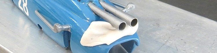
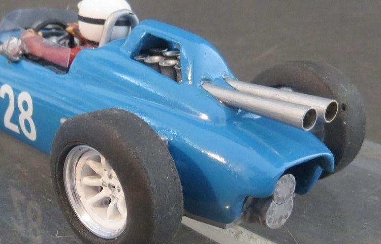
Once the mechanics of fitting the motive parts all together is solved, the next item on the agenda is the purely superfluous detail. All the bits that make the model instantly recognizable but don’t contribute one jot to the models performance. The megaphone exhausts will need fashioning and mounting eventually. Fortunately I have built several models which sport megaphone exhausts and the tools and the technique are at hand.
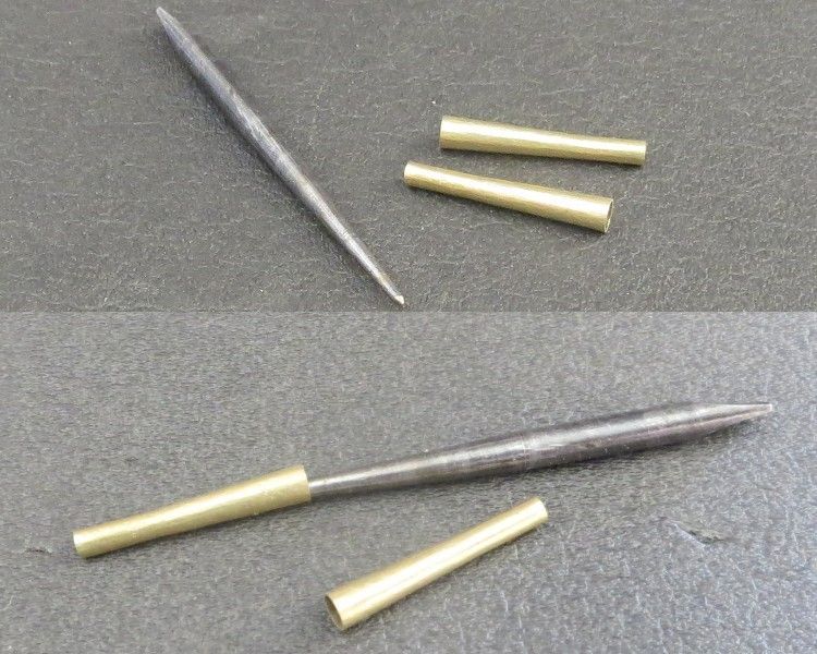
I bought a Japanese screwdriver kit as an apprentice probably forty years ago and to this day still have it in its entirety, and one of the most useful bits is a tapered mandrill; this I use to form the exhausts. A 20.0 m.m. length of 3/32nd o.d. copper tubing is cut to size and the mandrill is tapped lightly into one of the open ends; this has the effect of wedging the tubing on the mandrill, then, using a ¼ pound toffee hammer I then tap the walls of the tube at the pinch points until the tube comes loose; I then tap the mandrill back in place with three or four sharp taps (not too hard!) and repeat the process. After about fifteen minutes the mandrill is ¾ of its way through the tube and the desired tapered tube is the effect.
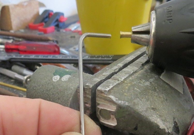
Next up are the intake ram pipes, these are designed to richen the air/fuel intake at high engine speeds on the real thing and are an essential to any model worth its weight in brass! Once again, an engineering background has left me with the ability to quite easily overcome this challenge. Firstly, I sourced some music wire which fits snuggly into the brass tubing, then, using a pair of round nose pliers I put a sharp 90° bend in the wire at one end leaving a 10 m.m. straight bit at the end.
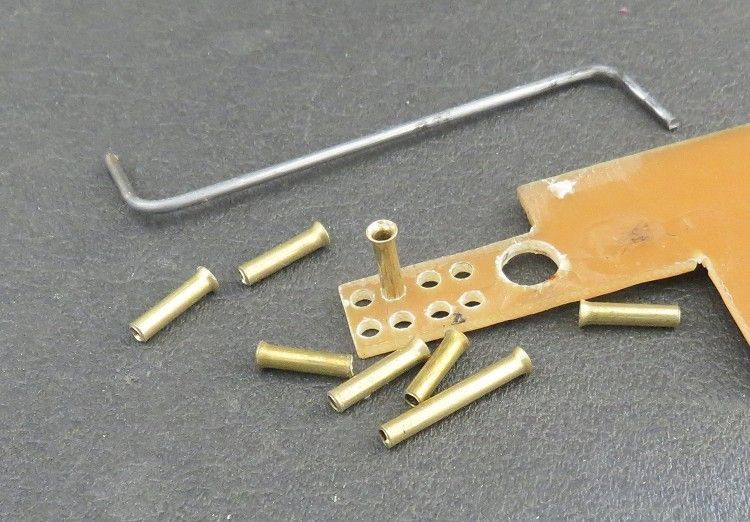
The brass tube is then mounted in a small rechargeable drill with three or four millimetres protruding. The music wire former is rested against a firm object and the drill and tube are fed over the wire. The drill is started slowly and a moderate pressure is applied to the drill causing the tube to flare at the end. How much flare required is pre determined. I tend to drill a small hole (gauge) in some waste circuit board and while flaring the tube I stop and check its fit in the hole gauge. Once the flare is a snug fit in the hole I know it is the right size!
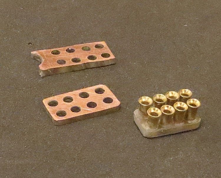
The hardest bit with this part of the model was getting the ram tubes mounted and close enough to fit under the rear body. A piece of PCB was cut to size and after carefully measuring, the tube holes were marked and drilled on the board. After three attempts I got the tubes looking respectable. These will get a spray coat of silver eventually but will not be fitted until almost the end of the build to prevent damage to them while working in other areas; the same goes for the exhausts.
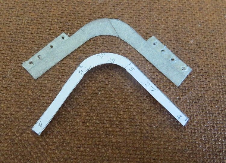
Next up was the suspension detail. I decided to replicate all the tie rods and not just some of them, this was easy enough and the remit here was to make them easy to fit. In the eventuality of the body needing removing it is essential that there is no necessity to remove other detail before this can be done, so the top rods will be attached to the body and the lower rods to the chassis and these will separate easily when the body needs to come off and also hopefully won’t get in the way if work needs to be done to the interior for any reason.
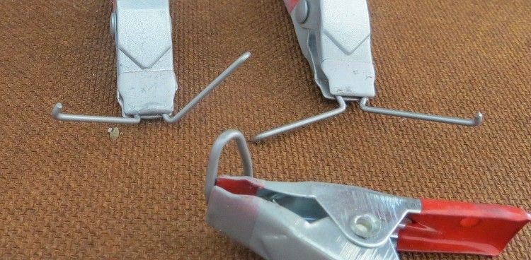
The material for these is 1.0 m.m. music wire, this is cleaned firstly as it will be easier while it is a straight rod than a bent one. The rod positions were calculated from scale drawings off the net and bent to shape. The short ends will fit into the wishbone detail and the longer ends will spot solder onto the top of the chassis.
Once in place the soldered areas were tidied up with a file and a sanding board. I fitted one rod at a time and after each rod I positioned the body over the chassis. Where the body touched the rod I marked its position on the body side. Using a round file I then filed a recess in the body side until the body fitted snuggly over the chassis again, I repeated this for the remaining rods, one at a time.
The top was a little harder; brackets had to be made to resemble the top control arms and once made, fitted to the body. The arm would also need to be angled up so that it cleared the collar on the inside of the wheel. After some careful filing, enough space was gained over the top of the front axle mounts and the arms were epoxied into place. The rear presented a similar problem but using similar techniques, the rear control arms were fitted snuggly in the rear, again, over the rear axle mounts.
Once cured (two to three days), the upper tie rods were made and fitted to the body. The rear ends were fitted to the control arms and again working from the drawing, the long ends of the rods were mounted through the body detail and secured on the inside, but I am getting ahead of myself here; This was all done after the body was painted to prevent paint getting on other paint and to stop the risk of damaging the finished job before it was finished.
Where the rods fit into the control arms I carefully soldered the rods in place leaving an excess of solder in place. I then applied superglue on the point of a modeler’s knife to the underside of the joints, this filled up any airgaps in the joint and helped hold the arms in place. Once dry they were sanded smooth. These parts are not specifically under any kind of stress while the model is running, and the only risk is that a wayward slotcar ‘T’ boning the model may cause some damage. But time will tell and I am fairly happy with their fixing to the model.
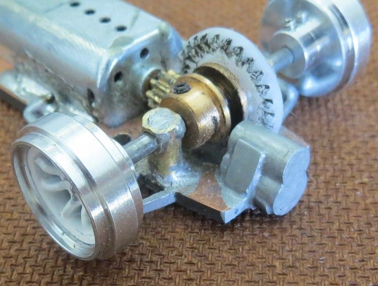
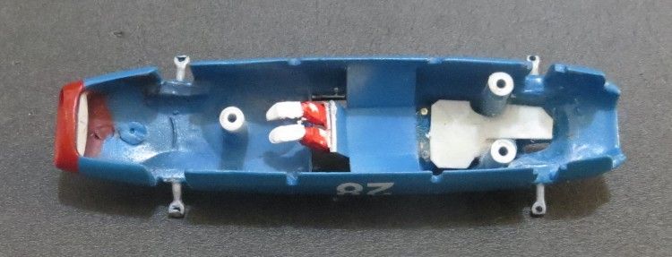
Another piece of detail was the gearbox, again, purely superfluous but an essential part of the model spec. I didn’t even attempt to copy the real thing but merely created a reasonable copy of a twin shaft synchromesh gearbox of the age. This was trimmed to size and offered up to the bottom edge of the rear chassis. It was eventually trimmed to size and to allow the contrate to clear on the inside. This was then epoxied to the rear chassis and brush painted in place.
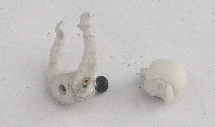
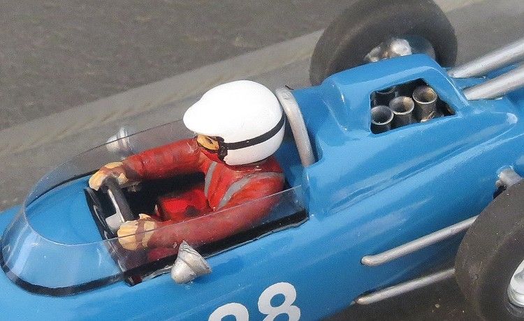
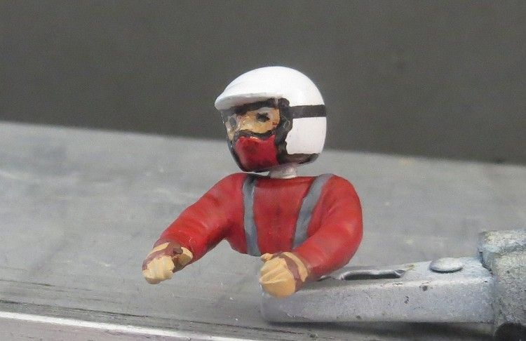
Other detail to be made is the driver, the windscreen and other cockpit detail. The driver was a trusty Fly driver trimmed to size and having his arms relocated to match the new driver position. Because of the motor it is inevitable that there will be compromises, and the driver had to loose parts of his body and legs to get him to fit.
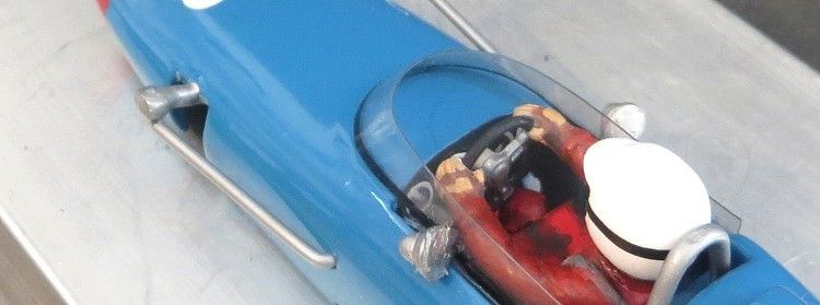
The drivers lower torso and upper legs ended up as painted renditions on the motor cover. Some lower leg detail was salvageable even though it is barely visible from the outside. The steering wheel is from one of Pendle Slots famous driver kits. This is a reasonable diameter and doesn’t appear to large in the cockpit, as well as fitting the driver well too.
The windscreen is also well documented in other scratchbuilt reviews (see Lotus 24 in scratchbuild section) and was simple enough to make. With the aid of a hole template I designed a screen on some copy paper and tried each screen against the model till I got the right size. I then stuck some masking tape onto a piece of clear plastic (from a cake box of all things!), this allowed me to draw on it, and I proceeded to replicate the screen on the tape. Some careful scissor work saw the new screen appear. The screen is attached by gluing the bottom edges of its lower sides to the inside of the cockpit. This piece of screen will need to be part of the drawing before cutting it out.
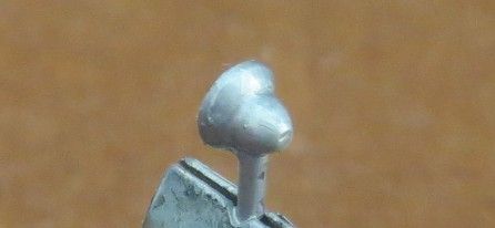
Getting close to the end now and some other minor detail needed are the rear view mirrors. These are the Tex ‘Torpedo’ racing mirrors used since the early days of racing and are really quite simple to make. A piece of polystyrene tube (small diameter) is placed in a drill and the open end is sanded into a cone shape. A piece of solid rod which fits snugly inside the tube is then turned down to a bullet shape. The rod is then inserted into the tube ‘et voila!’ it is then a simple case of inserting a piece of small diameter music wire into it’s side and to paint the finished article!
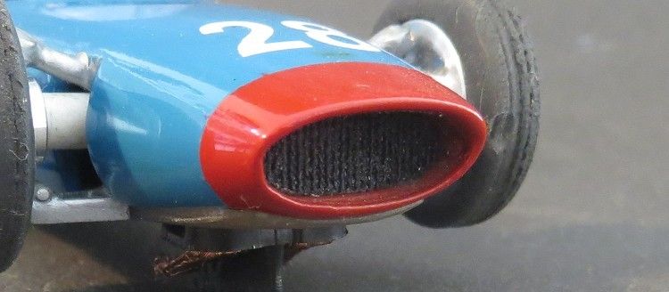
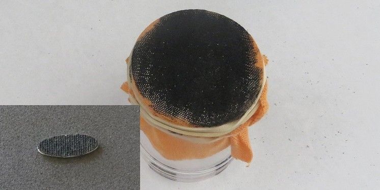
Last but not least is the paint job, I’m sure we all have our own methods of painting and this model will get its share of colour and clear. Decals are from my existing stock of numbers but for those without I’m sure Patto’s place will have more than you will ever want. Another ‘last job’ is the grille in the nosecone. I tried various textured plastics and effects but in the end I went for a simple fix. I stretched some cotton fabric over the neck of a jar and gave it a couple of coats of clear lacquer which I let dry hard. Once cured, I gave it a couple of coats of flat black. I cut a blank oval the size of the opening out of plastic, I then glued the plastic to the back side of the cloth, and when dry, lightly rubbed off the ‘fuzzy ‘ bits and eventually cut the oval out of the cloth, and another ‘voila!’ too easy!
The model was track tested in basic bare chassis / body form before it was painted and detailed so I am already pretty much aware how it will go. The tyres have been trued and seem to hook up well on my local track (flat painted board), but I suspect MJK’s will become the tyre of choice for regular racing. Wheels, tyres and inserts were from Pendle Slot and suit the model. Braids are medium soft and should be suitable for most tracks. Although it is a Ninco racing guide, the guide depth has been increased by squeezing it in a vice to improve its stability on routed braid tracks.

So that is it, I have tried to let the reader know of the more difficult parts of the build but the fact is that the builder will need some basic and some intermediate model building skills. Things that tested me were things like the jig required to mount the wishbones in the upper body and hold them in the right place while they set; making the dash gauges out of plain decal paper; mounting the air intake ‘ram’ tubes in the upper body and fixing the megaphones to the rear body. Also, every time a coat of paint went on the body, the chassis had to be tried in place and wedge points filed carefully away.
But the two most difficult jobs were firstly, to build up the detail in the rear of the model and still leave space for the contrate; this consisted of delicately grinding away offending parts without destroying the detail; and finally, painting the body became traumatic when the clear coat blistered the finish colour coat no less than three times! I had been using Tamiya enamel and something was not agreeing with the Tamiya clear coat. Eventually I used acrylic clear and completed the paint job.
So, if you fancy having a go at something like this don’t let me put you off! Once again I have added more skills to my scratchbuilding abilities and things can only get better. As mentioned at the beginning, the body was salvaged from an eBay scrapyard lot and is a particularly rare body. Now and then an unopened 60’s Lindberg kit comes on the market and it could be yours for a ‘buy it now’ price of $450.00