


.
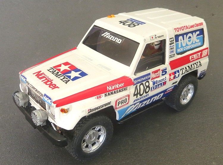
Toyota Landcruiser RAID
DAKAR 1990
by Phil Wicks
Every once in a while when I am relaxing and taking a break from my hobby I will sometimes turn to the best alternative; watching famous online auction sites to see if there is anything in the offing that I could have a bit of fun with….by that I mean buying something a bit unusual with the intention of building a hard to find racer, or looking for something to make a more unusual model, not necessarily for racing but something just to test the imagination and building skills; and hopefully help me call on more problem solving abilities which would come in handy further down the line.
Those who have been a visitor to this site before will know what I mean, and there are more than several projects in the scratchbuilding sector which demonstrate this ethos. I have to admit that some models could have had more attention paid to their detail, but more often than not the detail was secondary to the more technical challenges needing to be overcome.
1/32 DAKAR on eBay
When ‘kit bashing’ it is all too easy to shoe horn an off the shelf chassis into a static model and spend hours on a good paint job. To me in many instances the paint job has been more or less secondary to other build tasks. But I do have to admit that over the years I have spent more and more time with the finished exterior as build challenges become less and less with experience.
This model sort of falls into the ‘half and half’ category, by that I mean it started off as a mechanical challenge to see if I could create a model which might just be competitive with all the RAID and DAKAR vehicles already out there. As a group the local slotcar guys race “RAID†as one of the regular categories and at the moment the favourite (although not the most prolific) is the NINCO range of 4WD’s and pro trucks.
There is a fair share of SCX DAKAR trucks but it is hard to get these running as fast as the NINCO’s simply because the SCX RAID models have slower motors and have a pair of reduction shafts as part of the final drive. This reduces the top speed considerably, but, as we race on a fairly technical non magnet track it is possible to get the odd SCX flying to a degree where it could make the podium in the right hands.
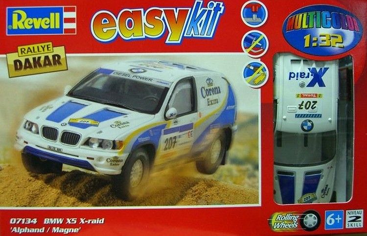
What is out there in the form of kits is not too bad. Revell do ‘Easy Kit’ kits which are already painted, and it’s a straight forward kit bash to get something up and running. A short list of models to choose from are the VW Touareg, the Mitsubishi Pajero, the Nissan pick up and a very nice BMW X5 RAID. Prices vary but they are out there and they make excellent models. See the Nissan Pickup in the scratchbuild section.
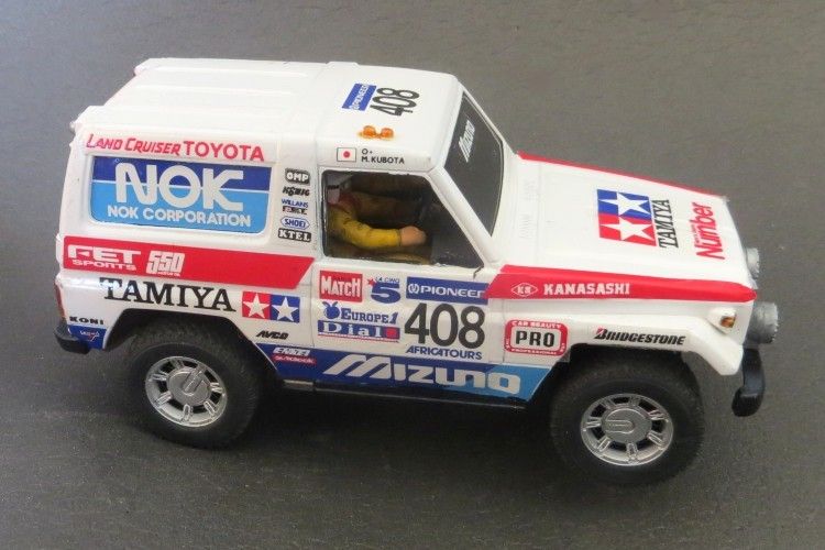
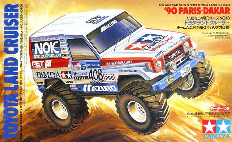
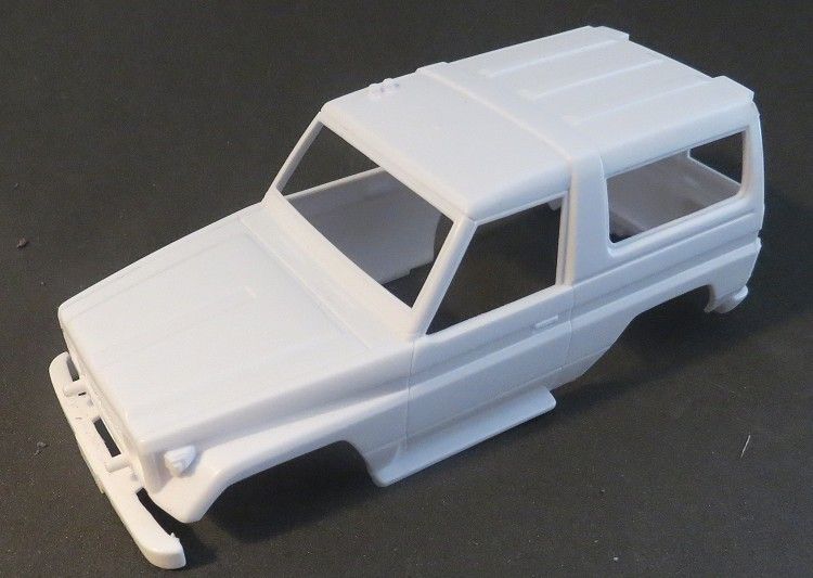
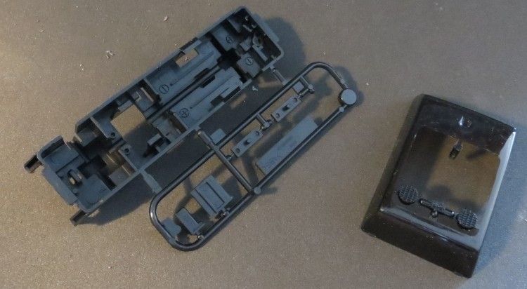
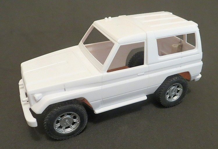
Other models on the market are a bit harder to find but the subject of this review can be found aplenty on most eBay sites. There is also a Landcruiser 100 in road trim from Tamiya. The Landcruiser actually comes as a motorized kit with what looks to be a 3 volt ‘S’ can and some very useable drive gears. The tinkerer may well be able to convert the chassis to fit their local track and where it would entertain for hours as an off road runabout, the chassis gears would be no good in a long term competitive conversion. I did actually build the chassis up for this model and it is quite neat and easy to construct.
Other models in the Tamiya range are the Toyota Hilux pickup, Hilux 4runner and the Prado.
Sale-fire.com
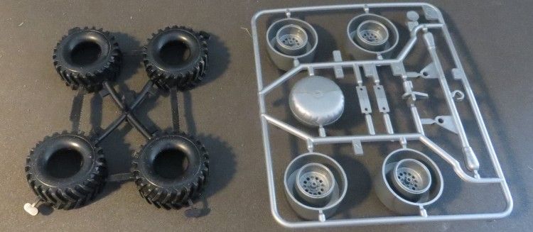
So back to this kit and what did we do to get it half decent on the track. First up was to decide what parts were to be used and what wasn’t. It was plain from the onset that the chassis supplied was not serious enough for the job in hand; especially the monster truck wheels and tyres, as great as they look I suspect they would generate all sorts of problems in a race.
So the decision was made to kit it out with a wixwacing PCB chassis and in doing so, it was going to be necessary to overcome several issues mostly related to its height off the ground.
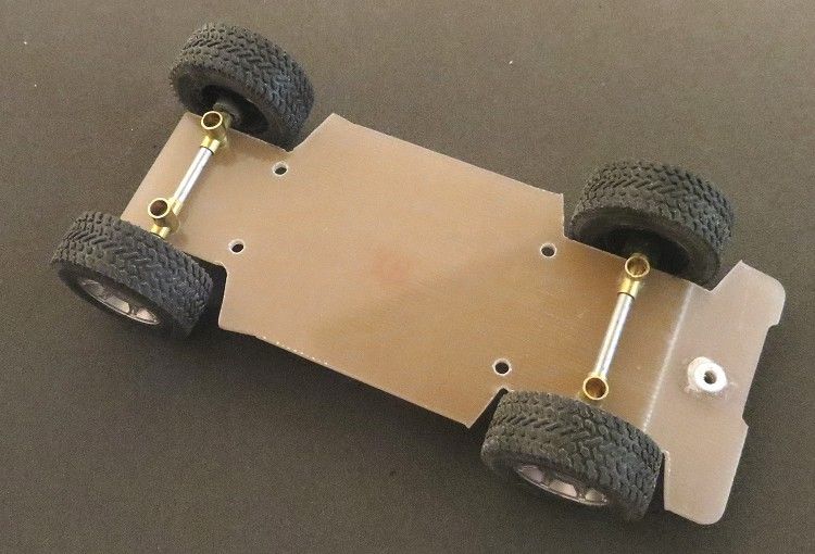
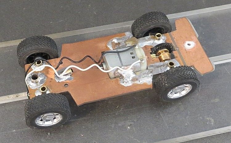
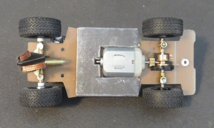
I started on the chassis. I was ly going to have the chassis hanging down a bit lower than the sills. This was do able but it is not an easy task and I viewed it as excessive for what I wanted to achieve, so the chassis was the usual flat pan with all components soldered on. One striking difference though was the necessity to mount the axle holders upside down compared to my usual chassis. But this was not a big deal and it just meant there was more detail underneath the model. The motor was tilted down and placed almost through the chassis again to keep the centre of gravity as low as possible reducing the necessity for excessive ballast.
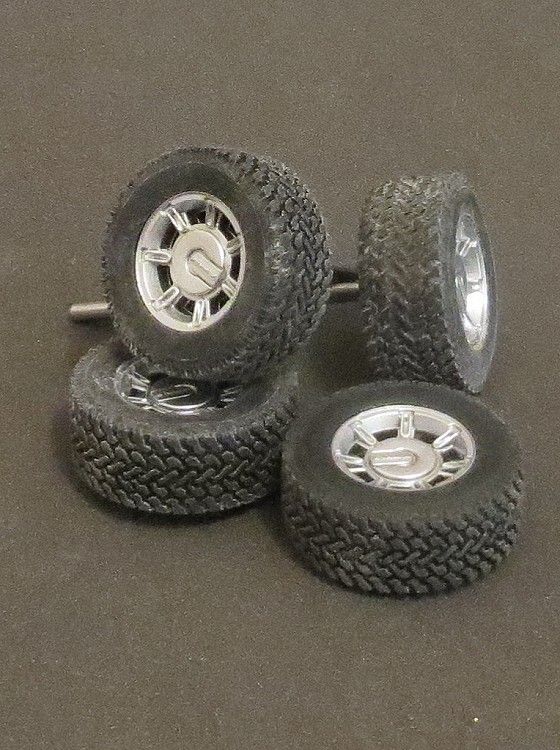
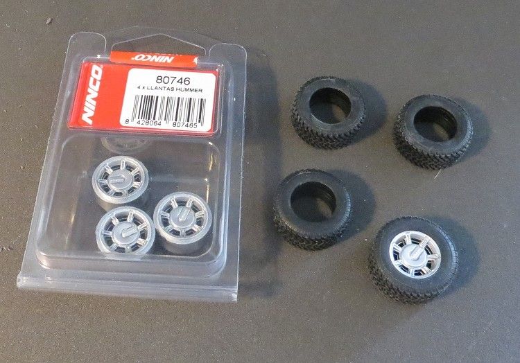
Wheels and tyres need to be a bit more sensible than the kit ones, but this proved to be more difficult than expected. Not all NINCO RAID tyres fit their rims so a match was required from off the shelf. I finally managed to get one of the retailers to trot out to their back room and physically put ‘a’ to ‘b’ and tell me the result and as a result, they managed a sale!! Not too hard! And the sale was a set of NINCO Hummer wheels and a matching set of NINCO Pro-truck tyres! I would dearly like to have fitted some raid type wheels but they are rarer than hens teeth and those that had them couldn’t confirm the tyre fit and suggested I buy them on speculation!?
Chassis components are as most of my scratchbuilds, but as already mentioned the components were mounted from the underside instead of from the top, although they were still soldered in place from the top side. One extra item up the front was a brace. This is mounted behind the guide at an angle of about thirty degrees; the reason for doing this is to take the sting out of a front end impact involving the guide (i.e. someone’s body screw wedged in your slot!).
Without the brace it would not be long before the guide tube would be loose in the circuit board. Once these components were in place I dropped some superglue onto the holes from the opposite side to the copper side, this soaked into the brace and guide holes very nicely and ensured a little bit extra security than just the soldered copper foil.
The chassis was now looking pretty good and final work carried out was the placing of the screw mounting holes and fixing the duck tail at the back. For this the board was scored three quarters the way through and bent up to fit the recess in the body rear. Once upon a time I would have soldered this in place but I have since discovered that with the careful application of superglue several times over a few days, the glue will fill the groove and set very hard in place; I have used this method successfully now several times. One word of warning, always handle superglue with care, use in a well ventilated area, and avoid contact with skin. If you can smell the glue when using it, you are inhaling it; you will need to wear an organic filter type disposable respirator.
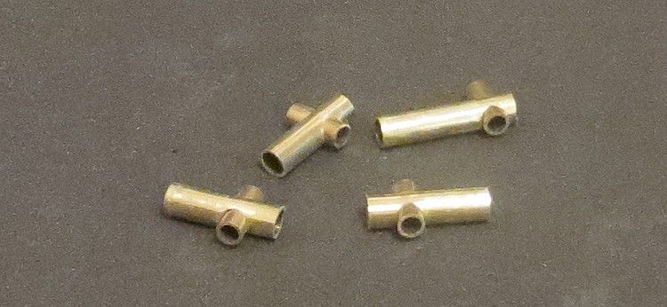
Having built the chassis it is then necessary to mount it in the body, and, once again, I have used a method I am very comfortable with. I have made the telescopic chassis mounting tubes on a lot of models now, and although they can look a bit flimsy, to date I have not broken one mount, and I have not stripped one thread. Common sense should always be applied when removing or refitting chassis’. You aren’t holding the axle or the motor in so screws need only to be nipped up at best; and if you are like me you may even run them half a turn loose or more depending on the evenness of the track.
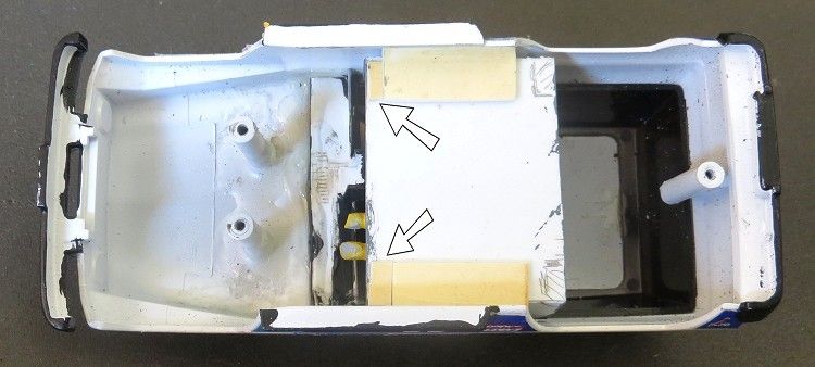
The rear mount was a bit of a poser but on this occasion I have glued the mount to the inside of the back doors. Alignment is simple. The mount is fixed to the chassis first and when offered into the body, a sliver of thick plastic is placed on the gap through one of the windows. Remember when gluing anything on any model, you will need to leave it to dry AND cure, for at least twenty four hours. If you work on the model inside this time you may damage the mount, you may also unknowingly weaken it, for it only to fail unannounced some short time later, so, if it’s glued or painted….. LEAVE IT ALONE FOR THE DAY!!
The guide tube was now going to be a few millimeters off the track, so an extended guide tube was created and I devised a novel way of keeping the guide from popping out. Normally a guide has a cleft end which pops over the guide tube and springs apart holding the guide and preventing it popping out quite unnecessarily, much like the 90’s type Scaley guides did. How I achieved this surprised even me. The solution was to mark on the outside of the guide tube the approximate place where I expected the top of the guide would come.

Then, using the small pipe cutter I use for cutting brass pipe for several jobs on models, I ran the cutter around the pipe three or four times, this caused the pipe to ‘choke’, i.e. on the inside it developed an annular ridge reducing the pipes inside diameter, this was caused by the cutting blade as it applied pressure to the tube wall and before it started to seriously cut the pipe the process was stopped. The NINCO guide was then inserted into the pipe and pushed over the detent! Excellent result, the guide is a snug fit in the tube and extra effort is needed to remove the guide from the tube over the ‘choke’.
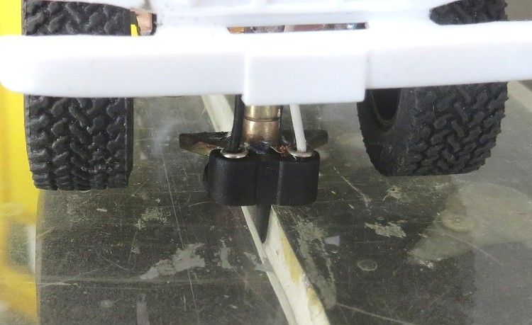
One extra item at this stage was a guide travel stop! With the guide sticking out of the body as far as it did, there was nothing to stop it spinning 360°! Again, a simple solution was to hand. A bracket was made in brass which fitted to the bottom of the guide tube. This conveniently stopped the guide after it reached about 45° or so either side of straight ahead!
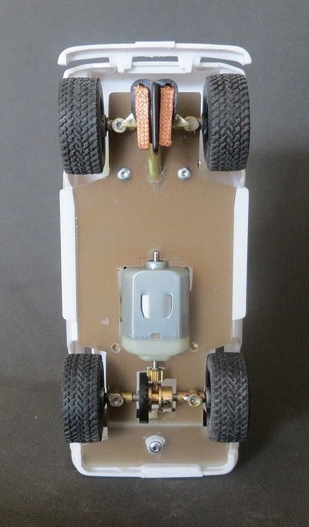
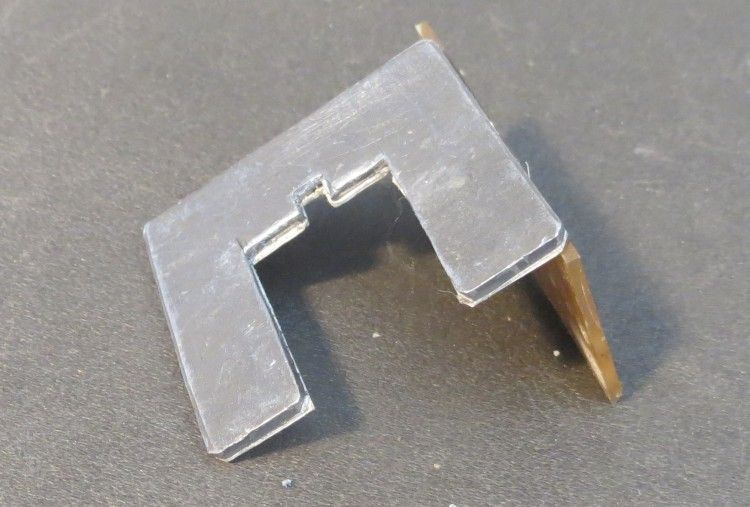
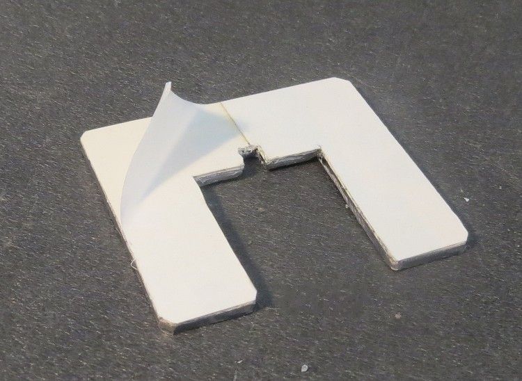
As a safety measure I soldered some custom cut plates to the chassis at the end bell end of the motor. Wheel wells were in close proximity to the motor leaving a very narrow piece of ‘land’ between the two. For piece of mind I added some reinforcing. That just about took care of the all important bits you don’t see and, as you can see, I have finished up with a robust chassis which should be able to tough it out with the best.
Next up before going too far with the decorations, I decided to give the model a run to judge how it handled and how much ballast may possibly be needed to make it a viable racer. On my local three lane technical board track it was lively but was prone to teeter on the edge of disaster on some of the tighter corners, ending in a roll over deslot, very much as I was expecting! After weighing some RTR models I decided to give the model a finished weight of 125 grams, so the body and chassis were weighed and the ballast needed was calculated.
At this stage the tyres hadn’t been trued and this could account for extra un needed weight, so I applied an amount of ballast for testing and took the opportunity, while at a slotcar meeting at the Caloundra megatrack, to give it a work out during a break. As expected, on the sweeping curves of Mt Perrorama the model was more than well behaved…….and quite quick!
Needing the weight as low as possible I decide to mount it on the underside of the chassis, which is quite flat and smooth. I have experimented with several ways of attaching weight to models which doesn’t cause permanent damage. Hot glue is good but sometimes, unless the contact areas are absolutely clean, the glue will let go some weeks down the road. Superglue is fine but it is also pretty final and if like me you like your models to be unblemished when they finish their racing career, then this is probably not for you as the glue will permanently mark the surfaces to which you have applied it; and you will also probably damage the model when removing it for whatever purpose. Contact cement also works and again cleanliness is the by word, as it is with a number of other methods and materials.
More recently I have been experimenting with double sided tape, obviously for flat surfaces. Early attempts saw the weight drop off the chassis some days or weeks down the track and the inherent stickiness of tape just didn’t seem to cut it. I determined the cause to be the less than maximum contact area between two hard surfaces, and the movement between the chassis and the weight; and in an effort to remedy it I tried using tape in conjunction with a medium which had some ‘give’ in it without it letting go. Plastic and lead expand and contract at different rates and I am sure this was the greatest contributing factor to the weight coming off unraced models! So let me now bore you with the current technique I am using.
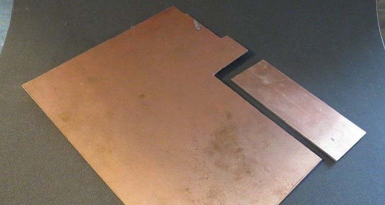
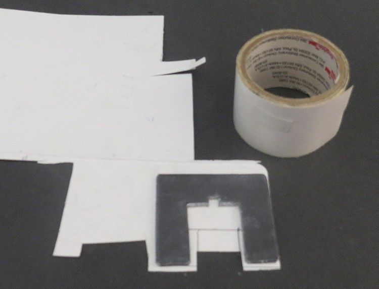
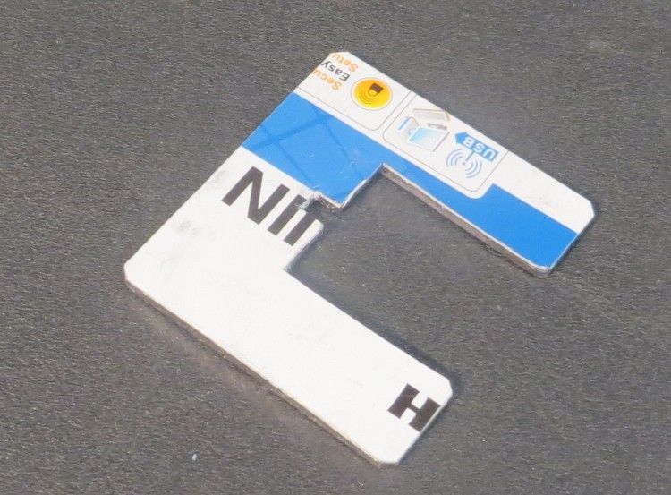
Firstly, the purpose of fixing weight on the underside is to lower the centre of gravity as much as possible. The weight is more effective and therefore theoretically, less weight is required to achieve the same result! This method is really only useful for models with flat areas on the chassis underside. But most models have some and therefore it works (mostly)! On this model the weight was calculated and a purposely shaped section was marked out on a piece of lead roof flashing. The piece was then flattened as much as it could be with a hardwood dolly and a flat surface. Care is needed here as too much flattening will see the ballast piece grow in area and reduce in thickness.
The ballast piece had some thin 3M® tape applied to its upper side. Some very thin card such as is found on blister packs was then cut roughly to shape and stuck to the double sided tape. I then placed more double sided tape to the upper side of the card and finally, after trimming to shape, this will be pressed onto the underside of the chassis. The purpose of using the card was to create a compressible packing piece which will allow a greater contact surface and a flexible layer between the weight and the chassis material. A lot of unnecessary work? Probably, but a problem solved, and, if you want to remove it, a drop of Shellite® (lighter fuel) applied with a modelers paint brush will see it drop off cleanly, and still be reusable! I have several race models using this method and they haven’t lost any weights to date since testing began (several months).
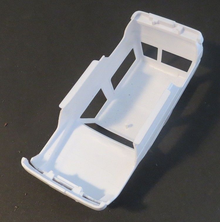
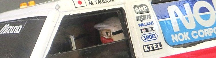
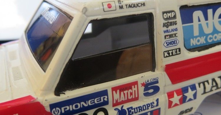
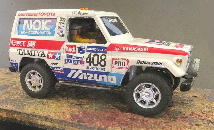
As already mentioned this model was an exercise in chassis building and I wasn’t going to spend a lot of time on the body, but with time to spare I have experimented elsewhere around the model and developed new techniques which may well be used on future models. One of the issues with the model is that it has a tinted glass section. Our class’s state that unless it is Aussie V8’s or MINI’s then all models must have at least a half driver’s tray and matching interior detail. But an interior you can’t see was a bit ridiculous so I ‘posed’ the windows. One, half down and the other fully down. That way we get to see Mr Taguchi who is driving this thing! With no drivers tray in the kit it was necessary to build a modest one from the ground up.
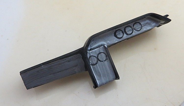
The interior was to be built on a platform which is suspended over the motor. The platform was easy enough but I had no suitable seats, so, fool that I am, I found a GT car seat in my spares bin and decided to copy it! Without going into too much detail I will let the pictures tell all, but the seats were cut and sculptured from some laminated plastic blanks using modeling knives and files and the old faithful dremel tool! Seat backs were formed out of thin plastic sheet and some thicker plastic laminated together was to supply the sides. Once cut down to the basic shape the rotary tool and a ball bit were used to give the seat the ‘bucket’ appearance.
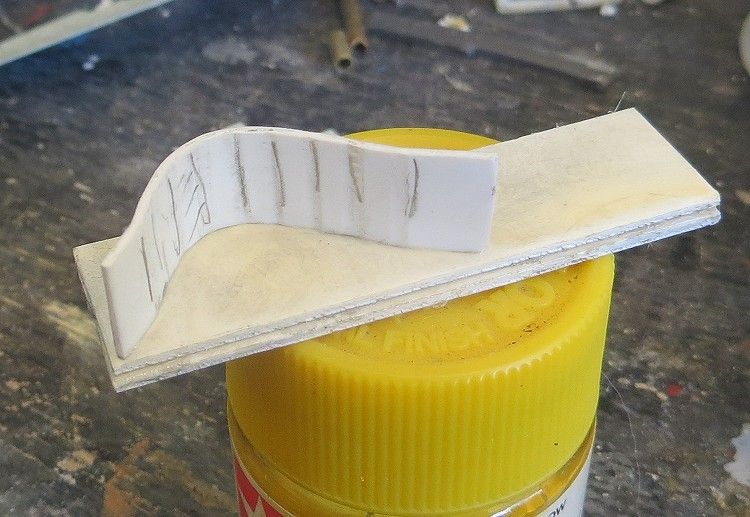
(above) the seat cushion glued to one of the laminated side pieces
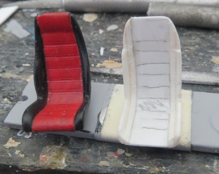
(below) the left seat is the master and the right seat is the first attempt
The drivers had their fare share of attention and more than their fair share of paint. These were (poor) resin copies of a famous brand and it took several less than enthusiastic attempts to get them looking presentable.
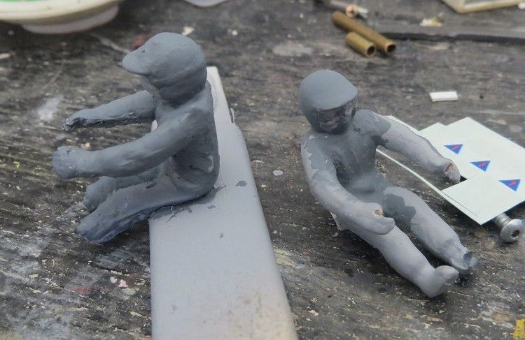
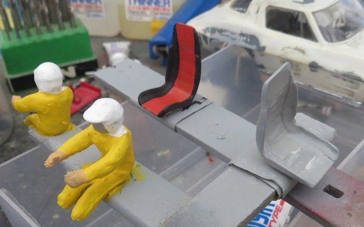
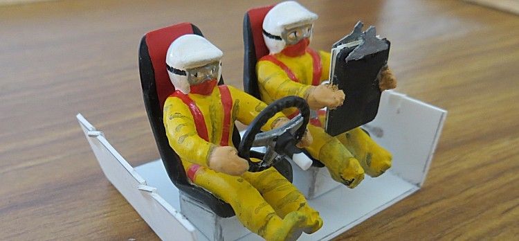
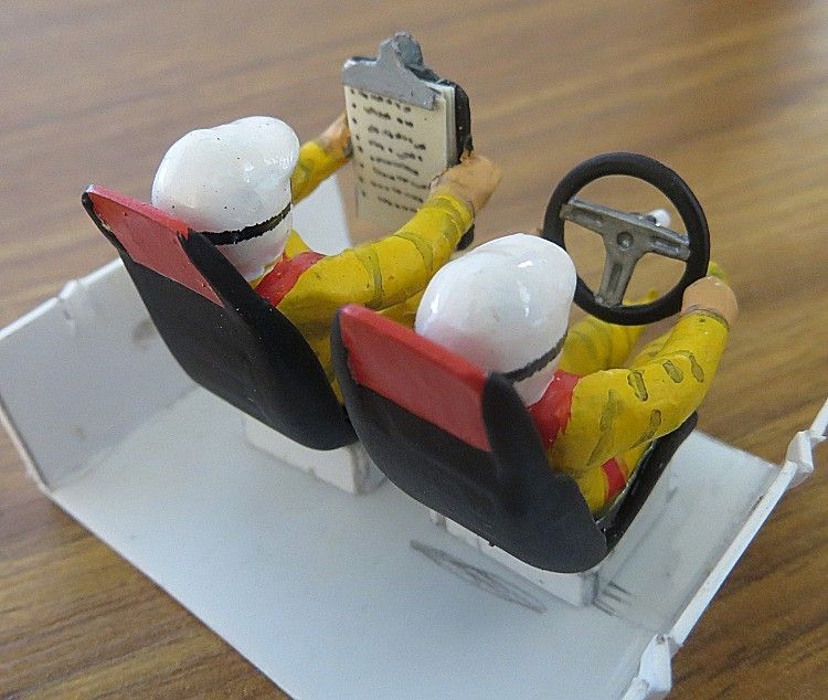
Here are both the occupants with their first coats of base colour, I will change my mind about them several times before settling on some basic poses. Both seats have been made and are in the process of being painted. Just for the hell of it the driver will be holding the steering wheel and the navigator will be holding a (somewhat oversize) clip board!
Both seats formed and one finished
Now that the windows are in the part open position it became essential that the model had a reasonable dashboard. Again, not wanting to get bogged down for ages in secondary matters, I eventually succumbed to the necessity of a reasonably presentable dash board. I do not profess that it looks anything like the real thing, but it does look like a dash and is now fixed into the body quite permanently!
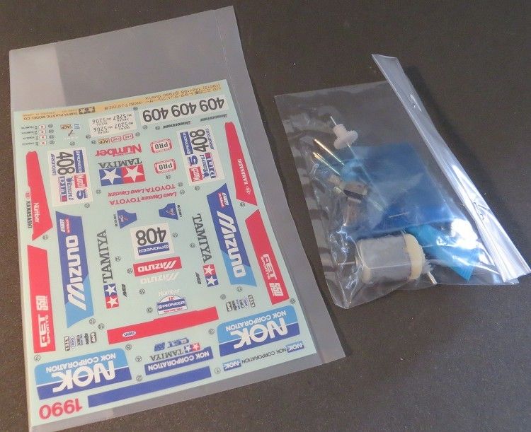
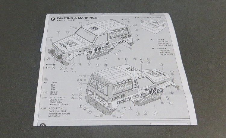
With the rolling chassis having been completed reasonably successfully it has been a case of tidying up the secondary detail. The kit comes with a self adhesive decal sheet. It also comes with a set of instructions as to where they should go but, if you have not applied these fiddly things before, or if you have and totally cocked it all up then take heed. The approach to the stickers is simple, and very much like the real thing. What is needed is a medium that will allow us to slide the decal about into its correct position without it sticking in the wrong place.
By the time you have pulled it off two or three times it will be scrap value. But fret not, have at your side a small take away container containing some mildly soapy water i.e. dishwashing liquid. After carefully pulling the decal off the sheet with a pair of tweezers, dip it in the soapy water. A quick dip will do, no need to let it soak. The decal can then be slid carefully into its position on the model. With your third hand you can gently roll out the water from under the decal until it shows signs of sticking. Once it has become attached you can then stroke or roll the decal removing the last remaining drops of moisture.
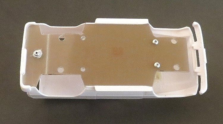
The last major job to be done was to fit the drivers tray into the body. Care had to be taken here as there is relatively a lot of weight resting on the driver’s tray in the form of the driver and navigator. Too much shaking about over long periods could see either or both occupants work loose or become dislodged and trapped inside the model God forbid! So, the driver, navigator and their seats will be glued onto the tray as you see it. The painting will be finished and the tray will be mounted in the correct position inside the body, but it won’t be directly glued in.
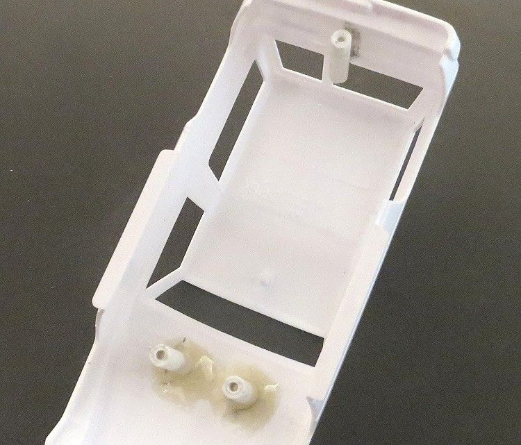
I have allowed for the top edge of the drivers tray to rest on the bottom edge of the window insert. The fix here will be gluing a couple of guide brackets to the body, these will rest on the driver’s tray and hold it in place. I have then glued a couple of small tabs to the front of the drivers tray to stop the tray slipping out backwards, these will be flexible enough to allow the tray to be removed for maintenance. But I think I am being over cautious and I doubt very much if anything will be going anywhere in the foreseeable future.
So, once again, a good track test will be the last thing to do, but I’m sure I have got it right having carried out a couple of ‘pre-decoration’ tests. Again a very enjoyable build and again the emphasis was on the mechanics of the build rather than the finish. There are several glaring anomalies about the model like the size of the navi’s clip board, the lack of feet on the occupants and the use of hummer wheels and so on……. but hey, unless you read this review then you’re never gonna know? Next thing is getting it past the scrutineers!
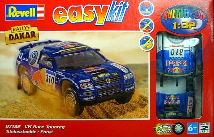
Once again plenty of fun putting this one together and a build time probably of about seven or eight weeks of spare moments here and there. Do yourself a favour and buy a Touareg or Pajero, these come ready Tampo’d and look a treat on the track.