


.
Airfix E type Jaguar
by Phil Wicks
I’ve had the Airfix E type Jaguar kicking around for some little time now and have never bothered much with it as I haven’t been impressed with its narrowness. In earlier attempts with small models handling has always been an issue and I didn’t see this model being much different. After a couple of successful Historic F1 builds I became tempted by the challenge, and summing up the skills I have achieved over the years I decided to give it a go!
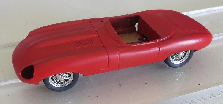
Rolling body, finished in flat Tamiya red enamel
I would be the first to admit that the main focus of my models has always been the automotive parts, i.e. axles, motors, chassis, transmission etc, and putting a drivable chassis together. Body detail has never been a high priority as most models get to go on the track and ergo, the paint job pays the price…. so let’s not spend too much time on it eh!
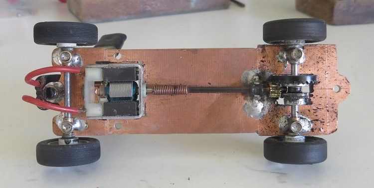
Rolling chassis with all components in place
This model is no different but I do admit to having spent a little more time than normal on the detail. This has been applied to interiors, drivers and upholstery, but I would be the first to admit that I still have a long way to go compared to some scratchbuilt masterpieces. But hey, there is always the next model or the next year for that, so lets focus on the business end of things for now.
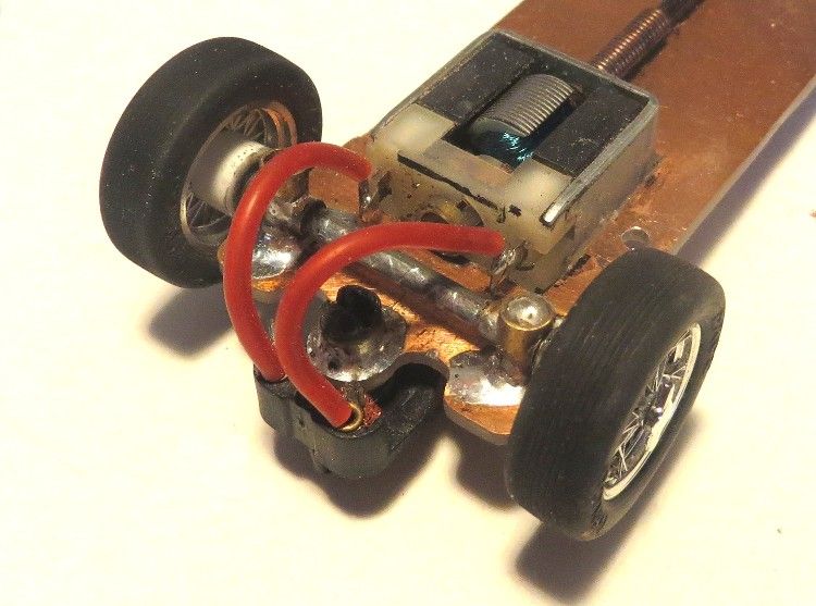
Front end motor …. glued in place!
First obstacle is the inherent instability with the narrow dimensions of the model. Do I ‘pump out’ the arches? Do I ballast it to the waterline? Or does it need a huge magnet slung under the rear? What about 12 m.m. wide fat tyres and cut out wheel arches? Perhaps all of these things?! Most of these measures would go some way towards fixing the issue of instability but at the same time it would turn the model into a freak! Let’s start with the obvious.
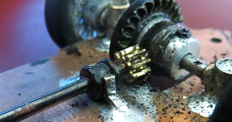
Rear end and tail shaft
The main issue is speed verses footprint. The model's track needs to be as wide as possible, in this case the tyres will be just scraping the inner wings (guards/fenders) and wheels and tyres will be modest but useful. In this model’s case I have decided to stay to scale and fit some Cartrix wire rims and a set of Ninco classic ribbed tyres (20x7). I will then need to ‘trim’ the model carefully with some lead ballast applied under the model and painted to disguise it.
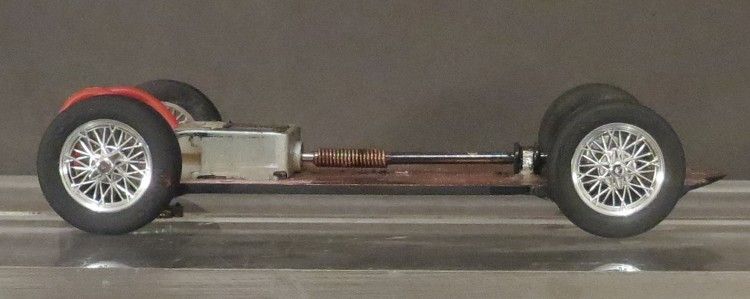
Rolling chassis complete
First up is to assemble the body as far as possible leaving space for some components that will follow. The chassis dimensions are taken from the body and the body is cut here and there to allow the motive components to fit. Also important is the sequence of assembly, there will be occasions when things won’t go in in turn, especially in the cockpit, so plan ahead and have a coupe of dummy runs if necessary before attempting any tricky maneuver.
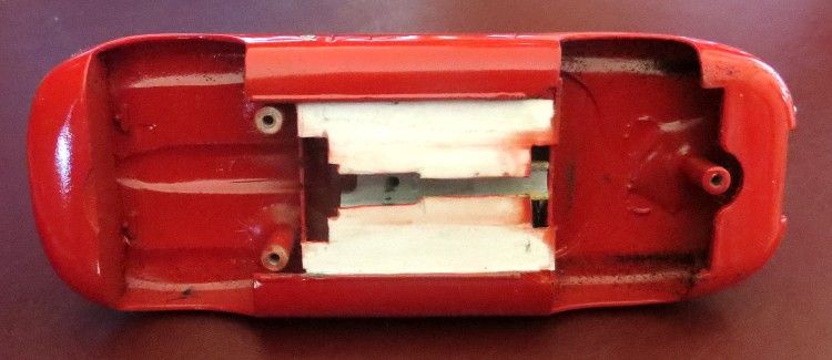
Recessed underbody
First to go into the body are the body posts, these will determine where the chassis sits in the body, and this has to be established before you can fit the axles and set the ride height! I have flush mounted the chassis to the body underside so now the tubular wheel and axle mount positions can be set. At this stage there is a big gap in the underbody where the floor has been cut out, but a new floor will be created and some material will be trimmed off the seat bases and other parts to compensate for the thickness of the chassis.
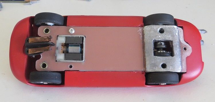
Chassis located in recessed underside…the ballast looks heavier than it actually is
With the axles in place, the drive shaft and motor can be mounted. The motor is mounted midway between the cockpit and the front wheel arches. The motor output shaft was sleeved with some fine brass tube and this in turn took the drive spring at the front of the shaft. A ‘C’ shaped shaft bearing bracket was made from 3.0 m.m. brass and soldered centrally in place on the chassis in front of the rear axle taking care for it not to stick out too far into the cockpit area. The crown gear is a 27z offset gear. The offset allows the model to sit a bit lower than it would otherwise do.
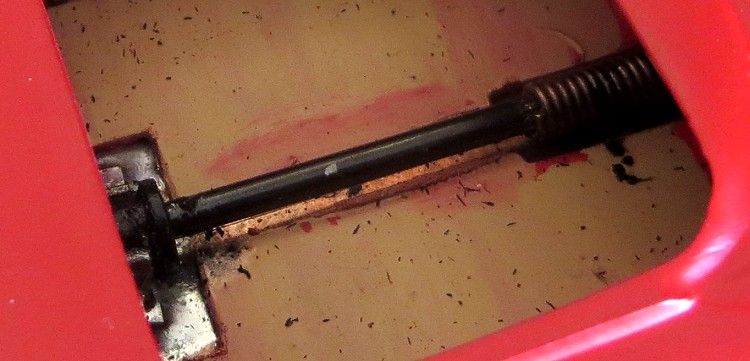
Drive shaft in the cockpit
The cockpit/body needed a false floor as the old one was removed to facilitate the chassis. This is required to support the seats and the transmission tunnel. Some thin polystyrene sheet was cut to size and glue mounted in the body. After it had cured for a couple of days it was slit along the centre, removing a strip approximately 3.0 m.m. wide. This allows the drive shaft to pop in and out when the chassis is removed. Always let polystyrene cure for a couple of days after gluing. It will remain soft for this period and excessive handling will see the glued parts become detached.
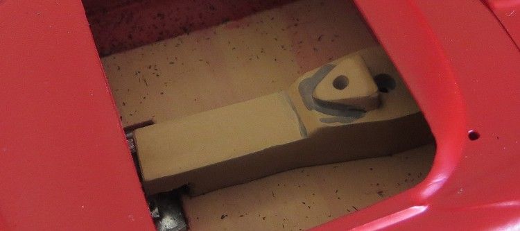
Transmission tunnel in place over the shaft
Once the floor is fitted, items like the seats, tunnel and driver can be made ready for fitting. Nothing will go in though until the interior door trims and dash are painted and fitted. This is where getting things in sequence comes in to play. The body will need painting now and the cockpit detail will want painting before it is fitted. The body was primed and tidied up using Tamiya grey primer. Next up the body received two light coats flat red which were rubbed down between coats with some coarse cotton fabric. 1200 wet and dry will also work as it is just required to smooth the surface a bit before applying the clear gloss. Be careful not to rub through edges and corners though.
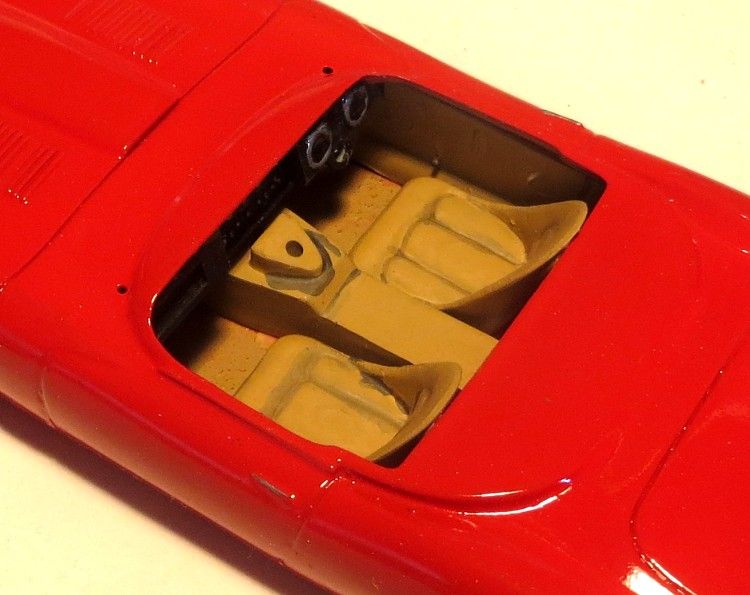
Cockpit furniture in place.
After the first clear coat silver detail and light colours were painted on and again once dry another coat of clear was applied. The headlight detail including covers was then glued in place. A day later the third coat of clear gloss was applied and then put aside for a coupe of days. This is where it gets tricky. The painted dash board had a bead of cement applied along its top edge and using tweezers, was then fitted in place through a slot in the underside of the chassis/floor. The carpet, door trims and seats had been painted in the interim and could now be fitted. The door trims were fitted through the cockpit and areas on the floor were scraped back to plastic so the seats had something to bond to. Once the transmission tunnel was glued the driver was next up.
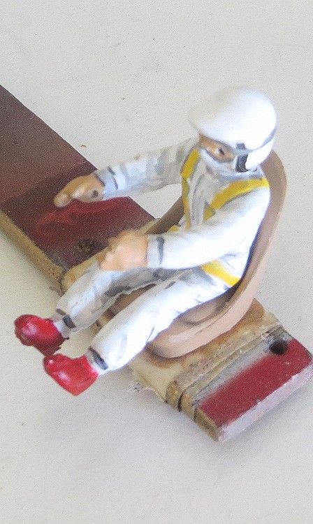
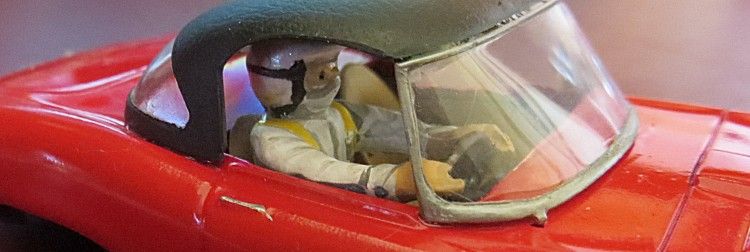
Driver!
The driver had been test fitted some days earlier and was considered a good fit after extensive scraping of his posterior and the seat cushion. One thing I did cheat at was to fix the painted steering wheel to the driver and not the dash! Mounting the wheel in the dash and then getting the drivers legs under it was not going to happen, so, as on a coupe of previous models, the wheel was glued into the drivers grasp and the whole when dry was offered into the cockpit. Some superstrength epoxy then fixed the driver into his seat. Overkill with the glue? not really; I don’t need the driver coming loose somewhere down the road after the soft top is on!
Test fitting
Needless to say the soft top and the windscreen are amongst the last things to be fitted. After the body was dry and before the third coat of clear was applied I took the liberty of mounting a pair of anodized (chrome) headlights inside their recesses. Again after curing I cleaned up the light covers and glued them in place with clear epoxy, which then got a coating from the last coat of clear!
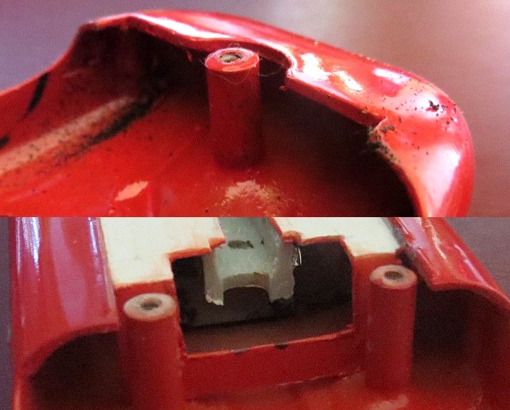
Front (twin) and rear (single) chassis/body mounts.
Soft top clearance is important too. We don’t need to fit the top only to find the driver is too tall and the top won’t go on (it has happened)! This will be the last opportunity to get the driver posing well in the cockpit. Try to avoid a plain driver in a plain pose with a blank face staring into the distance. I tend to have them looking away from straight ahead and not at the sun visors! Some careful sawing part way through shoulder and leg joints and some careful reglueing will give a far more natural look to the driver!

Body fixing screws DU-BRO No2 x 3/8â€
Button Head sheet metal screws
Lastly is the screen closely followed by the soft top. The screen has already been masked and the frame silver applied some time before. It’s now a case of getting it onto the body without too much trouble. Time for another dummy run. Blue tack will need to be used to support the screen while the glue is curing. Once you are happy with the screen fit, it’s time for the real thing. A bead of clear epoxy is applied along the bottom edge of the screen with a small paintbrush. The screen is then carefully placed up against the blue tack previously applied to hold it. Lower the screen into its locating holes and retry the soft top to make sure nothing has moved. The screen angle is critical as it will determine whether you are going to have any unsightly gaps at the roof join and at the roof base on the body. Clear epoxy starts to set after several minutes, so work carefully, but quickly.
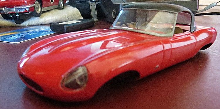
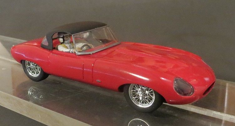
Clear parts and soft top installed
Again once cured the soft top can go on. This was masked before painting and the rear window was trimmed out of the masked area to make sure it was not messy by freehand brush painting. The edge of the masked area was given a thin coat of clear to seal under the edge of the tape. Once masked, the top was spray painted with Tamiya flat black. Yet again, each process was left at least overnight to ensure they would not pick up any handling marks from being too impatient.
Roof on! Phew!
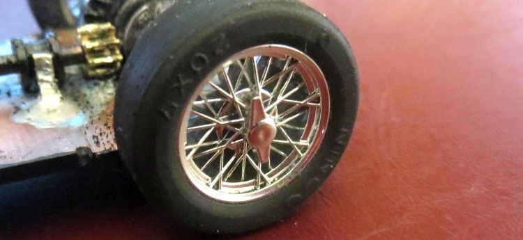
Cartrix classic spoked wheels and Ninco 20 x 7 natural rubber tyres.
Last job is the road test. If you have worked to the closest tolerances on the chassis you will find the need to perhaps make slight adjustment to get the model to roll freely. A tyre may rub under a wheel well in which case either the tyre or the well may need some material removing. The guide may need sanding to smoothen operation or to get the nose down a little. And, especially after painting, there may be the necessity to remove some paint which has worked its way into the chassis recess. Whatever the reason, the job won’t be over until those crucial early laps have been carried out satisfactorily.
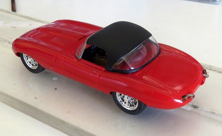
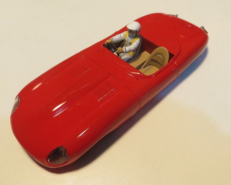
Completed model.
The model before ballasting weighed in at about 60 grams. I chose the little HO motor as it had plenty of revs (23,000 rpm @ 12v tested) and was not too heavy (11 grams) for the front of the model; it also gave it an NC1 type performance. Scalextric HO motors are readily available at a good price from eBay. On the track it is essential that the rear wheels and tyres don’t have too much work to do pushing the front along. The Ninco tyres have heaps of grip which seems to last years. I have models with ten year old Ninco classic tyres which, after a light sanding, still have close to their grip! Final weight after ballasting was 70.0 grams. Weight was calculated so that the rear of the model is slightly heavier than the front (53% / 47%) to improve cornering.
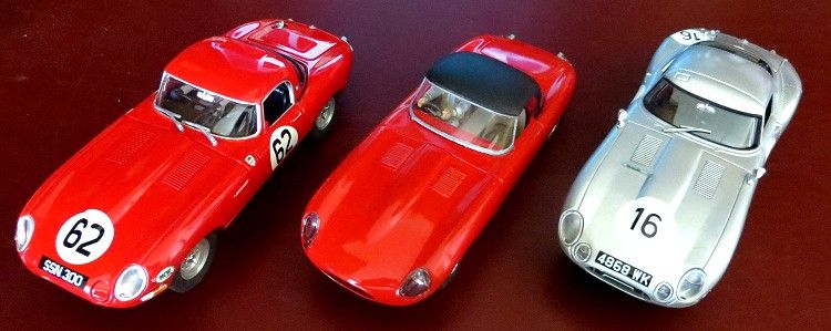
Stable mates
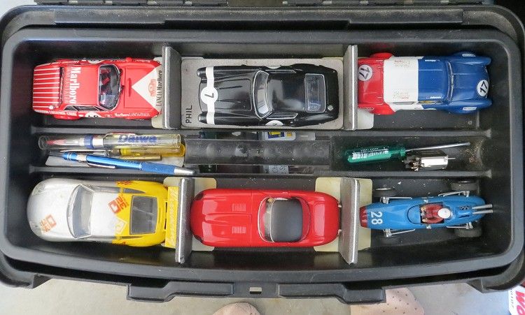
Initially I thought the model was a little too slim and short, but sitting it along side some stable mates it shows there is not a lot in it! The model was not conceived and built as a competition car, It is another of those exercises in model building and more to the point, it sits in the top of my race box along with some other classic scratchbuilds which I can whip out on racedays and do a few hot laps before things get serious. HO motors have already been used with some success by Scalextric in their Fiestas and some of their early trucks, so there is no doubt of their ability to entertain and after all, this hobby is not purely about speed (for some of us) but more about parity on the track so that the end result is left to the racer’s talent and not his wallet.
Spot the odd one out?
If you have another scratchbuild on the drawing board, especially a GP or F1, my advice is give it a go, you’ll be pleasantly surprised!