


.
Ocar
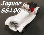
C type Jaguar
by Phil Wicks
The C type, or to give it its official title, the Jaguar XK120C was born of an idea put to company owner William Lyons. Some members of his staff were of the opinion that, with a few modifications, their XK120 would be suitable and successful in motor sport. Initially, a lightweight aerodynamic body was built to house the motive parts, These parts being modified from standard road going specs like larger valves, high lift cams and larger carburettors. Eventually, three cars were finished for the 1951 Le Mans.
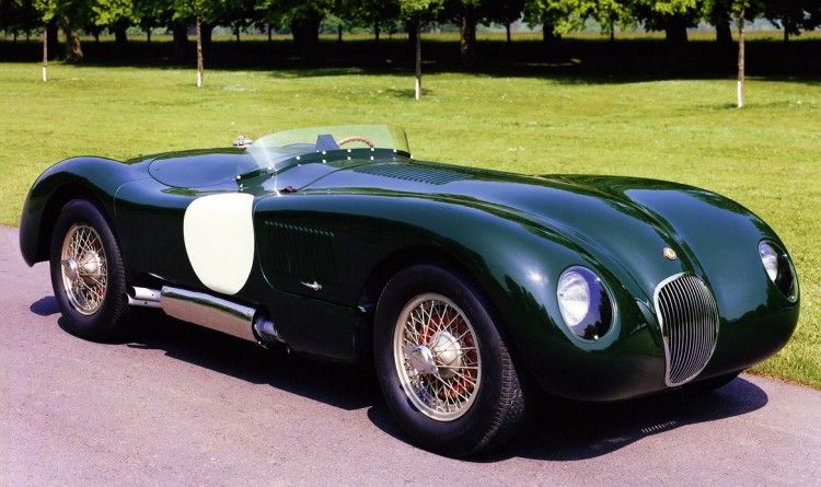
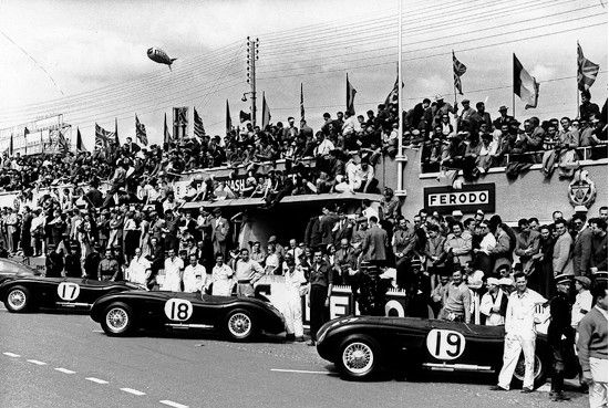
With what was to be a star studded line up of drivers, Jaguar achieved victory on debut with the Peter Walker car coming home first. But disaster struck the following year when untested cars with the new streamlined bodies retired early, all three stricken with overheating issues. Undaunted, Jaguar went on to other endurance race victories and in 1953 the team returned to Le Mans undaunted, and very confident. They had a new secret weapon, front disc brakes! These allowed the drivers to leave braking to the last minute without the fear of dreaded brake fade half way down the stopping zone; something which was in the ever quicker running sports cars of the era.
By 1954, international motorsport was going hard and innovation was the key to success. Mercedes and Ferrari had by now cottoned on to what sports car racing was all about so eventually, and inevitably, the C type gave way to its big brother the D type. Again success was in store, and Jaguar's racing career was well and truly underway.
Once again I have succumbed to the attractions of fifties sports cars and the C Type Jaguar is my latest in a long line of fifties classic. Not a particularly difficult build but I did spend a lot of time especially developing the steering. The greatest problem was to be pragmatic in its design and operation. Too many manufacturers that do make scale models with steering tend to reproduce in scale what the 1:1 had, OK for static models but sometimes significantly inadequate for the rigours of 1:32 scale model racing.
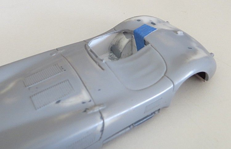
The body’s first coat of primer and the driver’s tray taped into position
Contrary to popular belief, scale models of this size cannot incorporate the dimensions and dynamics of a modern steering geometry set up, prime cause of this is because it is almost impossible to position swivel joints inside the edges of the wheel rim. On a real car the camber and KPI angles theoretically cross each other inside the dimensions of the wheel and at a depth of three or four centimeters under the road surface. This allows the wheel at point of contact with the road to ‘turn on its spot’ thereby taking up minimal space under the wing/mudguard and reducing the effort required to turn the steering. A scale model does not have the facility of a hollow wheel to locate this type of steering so, we have to make do with steering hubs which rotate around an external turning point which takes up space in the wheel wells which is otherwise at a premium.
Jaguar Heritage.com
Le Mans results 1953
Secondly, an essential part of front axle operation on a small scale model is the necessity for the front wheels to come firmly in contact with the track surface during cornering. This minimises the tipping moment generated by a model’s tendency to roll in corners, if this isn’t controlled, stable cornering speeds will be greatly reduced. Most model steering units with the exception of the F1/Open wheelers, do not achieve this and therefore render the model ham strung! On my model, the wheels are play free and in good contact with the track at all time.
So why worry about steering? Simple, it decouples the front wheels eliminating drag and sideslip problems generated in all corners; no need to coat your front tyre treads with nail polish / superglue, no need to fit so called hard rubber front tyres! That must be worth a few tenths!
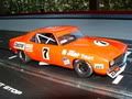
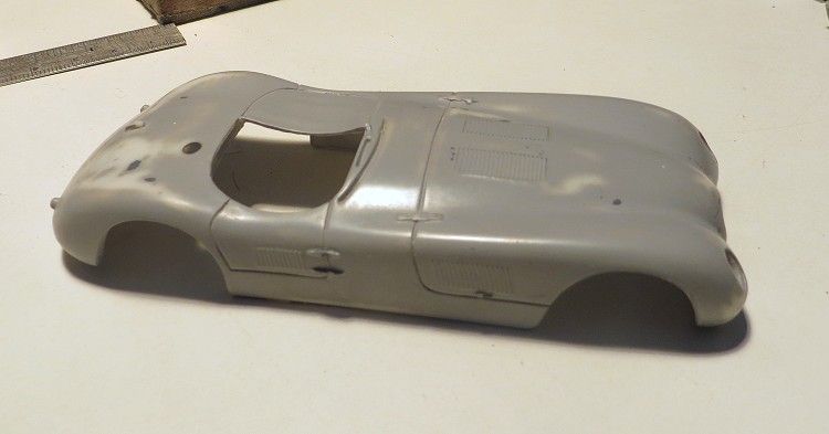
Steering isn’t the only innovation I have incorporated, there is some serious modeling to be done to this eBay ‘Ocar’ model. I have explained a thousand times how to paint your model so I’m not going there this week and you’ll need to look through my scratchbuild archives if you are having painting problems.
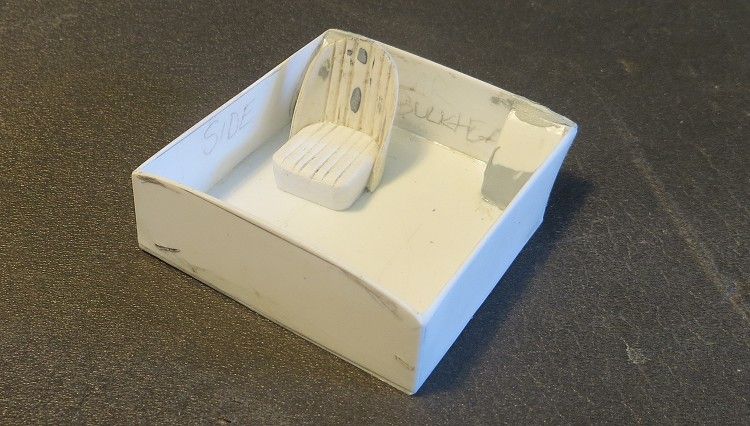
I have a single bucket seat from and old Airfix Frogeye Sprite and decided to copy it instead of using it, that’ll be used time and again on future models, but the pictures should be self explanatory from here on in.
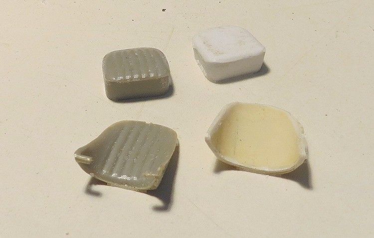
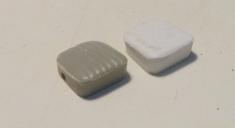
The seat ‘squab’ is a laminate of three layers of polystyrene sheet glued and wrapped around an seat back and clipped in position while the glue is drying. The seat cushion is a couple of pieces of 2.0 m.m polystyrene sheet formed into the seat shape after the glue had dried.
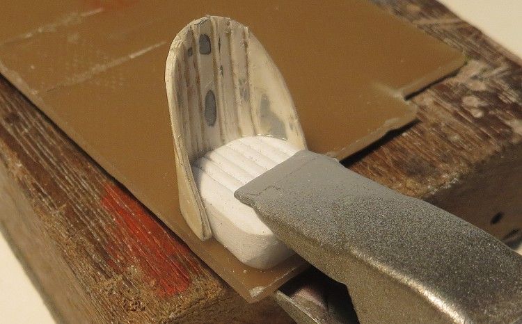
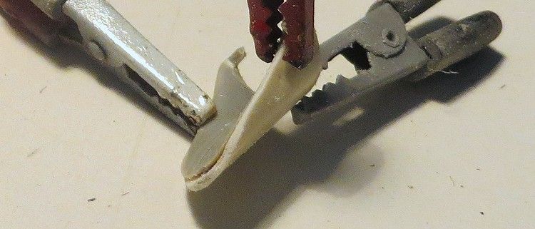
The seat cushion was clipped to some pcb and the squab was trimmed and profiled then stuck to the back edge of the cushion.
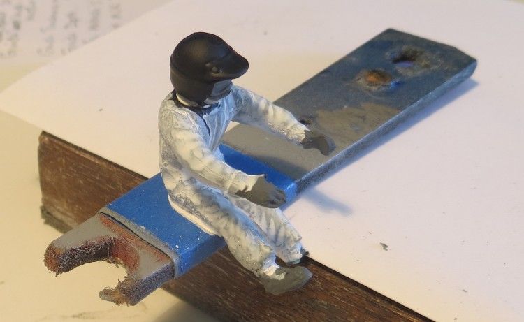
The driver is a resin casting of a Fly driver and as such needed a bit of work, this is the driver in grey primer with a first coat of flat white.
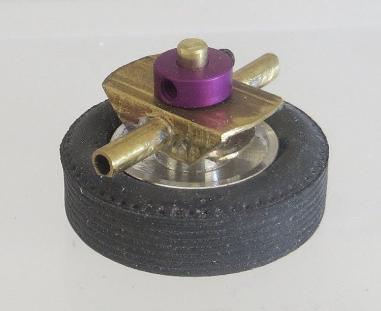
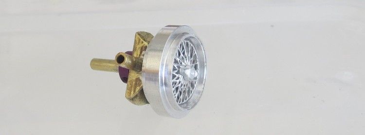
This is the steering hub, a bit complex but it does work well. The rear boss of the wheel passes through the brass box and the inside end of the stub axle is centered and tensioned by the purple ring.
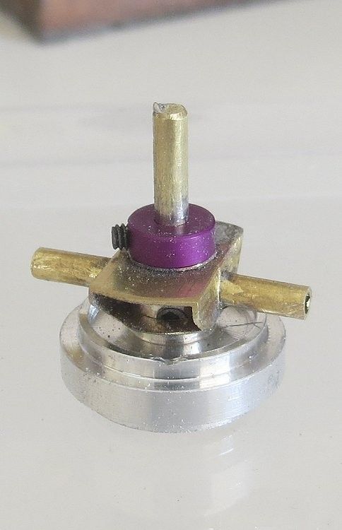
To ensure all the swiveling parts stayed in line I made a couple of jigs which held the top and bottom swivel pins in alignment while they were being soldered.
The end result is a compact steering knuckle which works well and has minimal slop, which is a curse on some commercial steering systems. More importantly it doesn’t take up much room in the wheel well and has a compact turning arc.
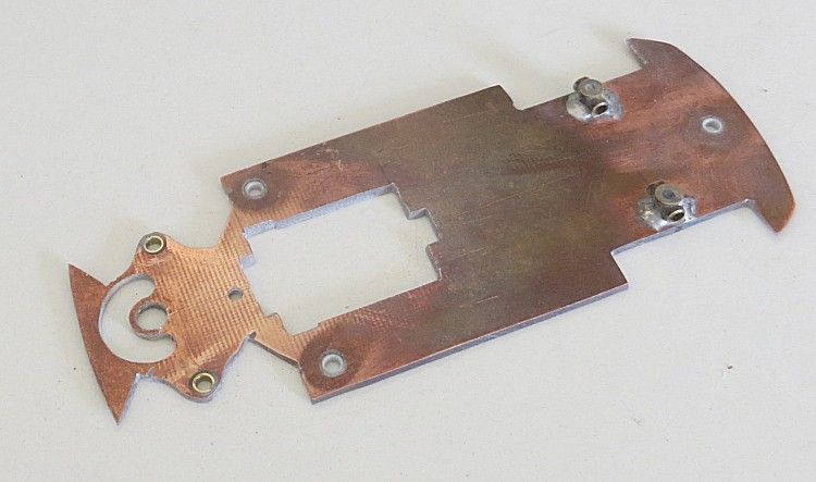
Notice on the chassis I have bushed out the steering swivel points to aid longevity, and I have sleeved the body screw mounting holes to make it more quiet; well, that’s the theory!
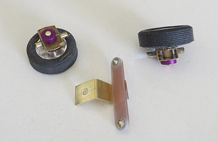
Assembled steering components
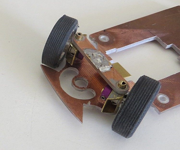
The hub assemblies locate in the chassis and are held in place by a top brace, which also allows room for adjustment/alignment of the steering components after drilling and filing.
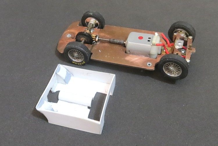
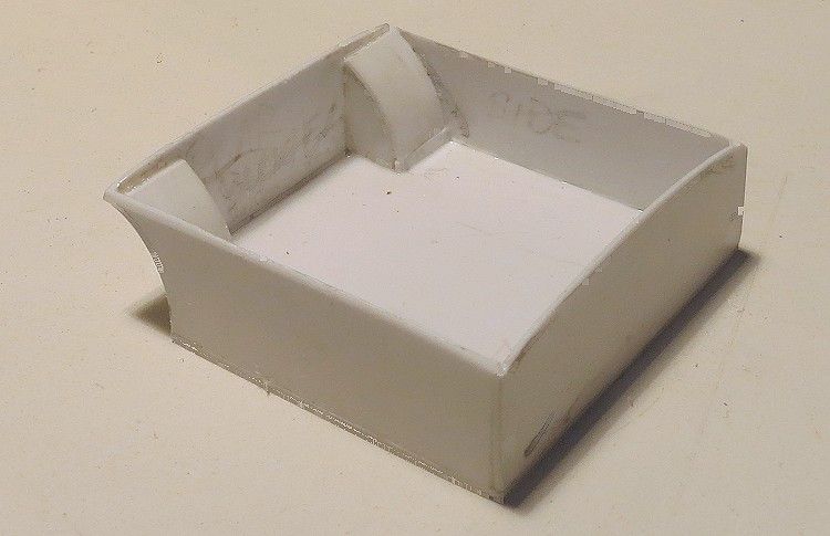
While all this is going on there are other things to do between the gluing and painting intervals. The model gets a full drivers tray as intended.
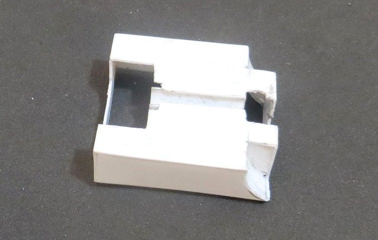
The tray is designed to slip in and out of the body at any stage wit no reason to fix it in, but I will be gluing it into the body just for peace of mind.
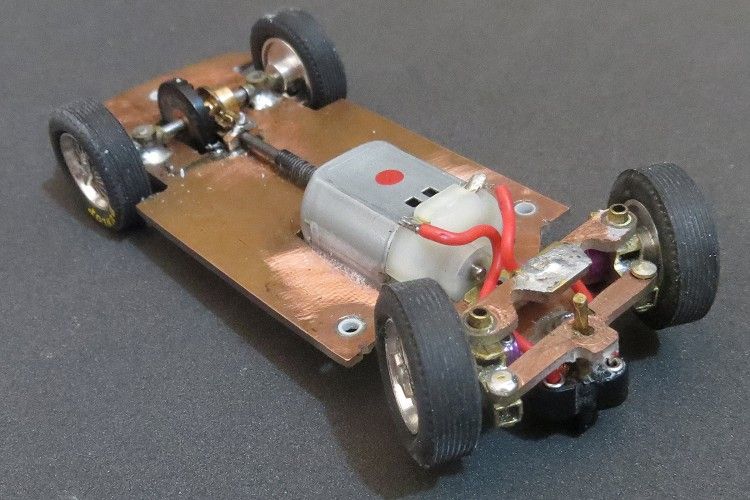
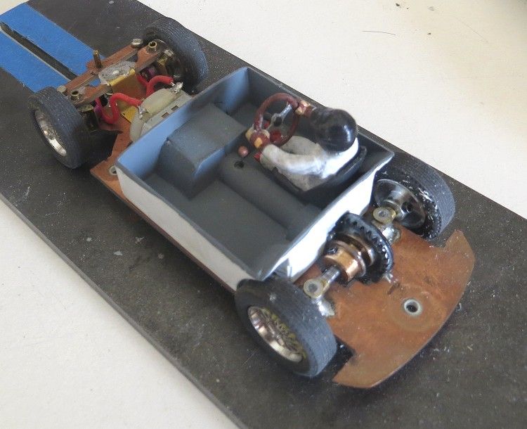
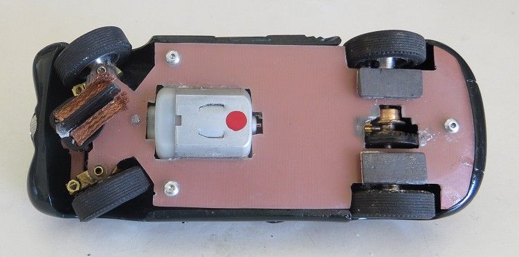
The completed chassis with assembled steering.
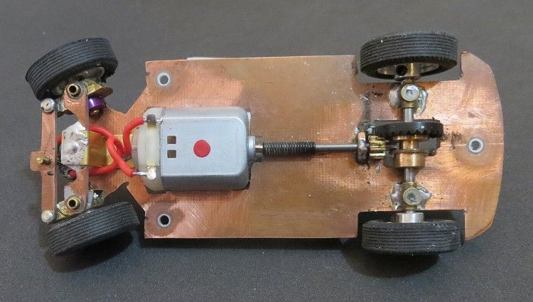
The red dot on the motor helps me identify what it is at some time in the future. In this case it is a Cartrix TX1 12,750 rpm @ 12v
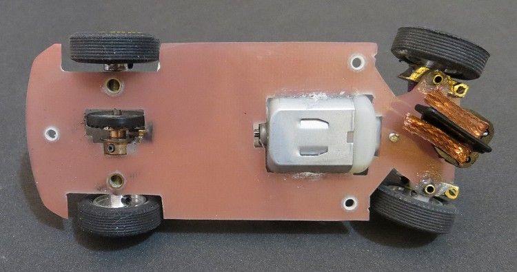
Neat and tidy is the way to go!
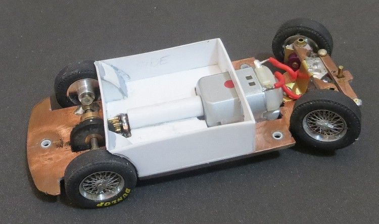
Test fitting of the driver’s tray, this needs to be done before fitting it out with seats etc.
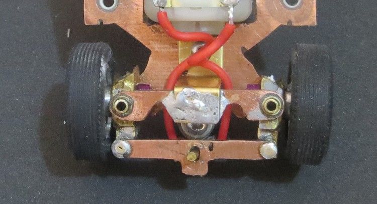
The ‘tie-rod’ has an elongated hole in it which takes the steering pin, which is drilled and glued into the top front of the guide
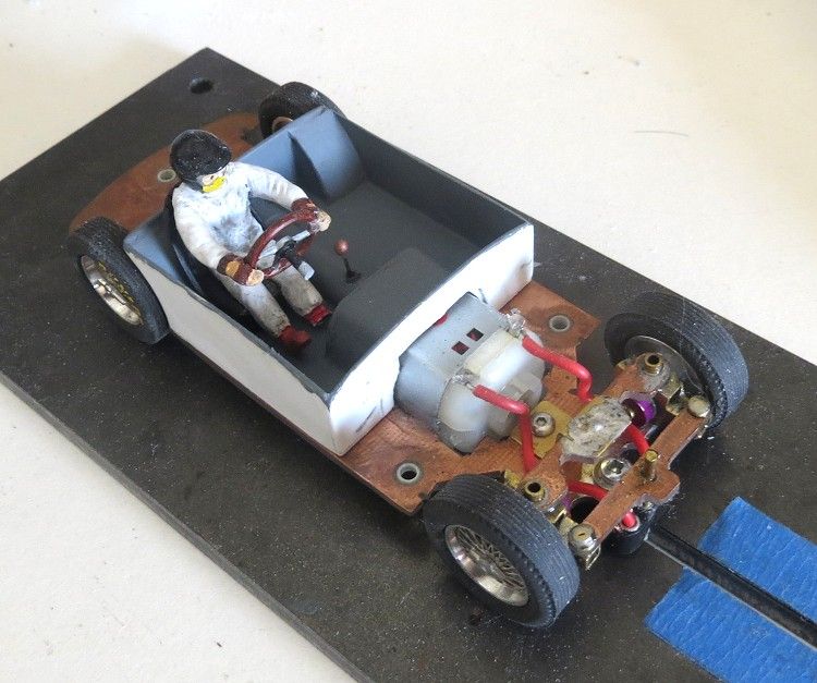
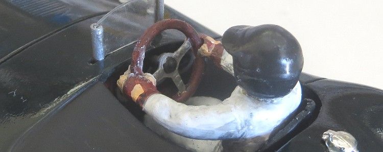
Drivers tray in situ on the completed chassis. I have glued the steering wheel into the hands of the driver. This eliminates the trouble of trying to slide the driver under it or trying to fit it to the driver after assembly.
You even get a steering wheel and a gear knob!! There is also a fancy dash fitted in the body! Trust me!
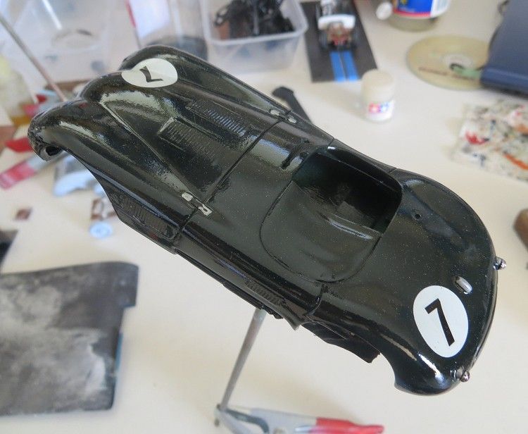
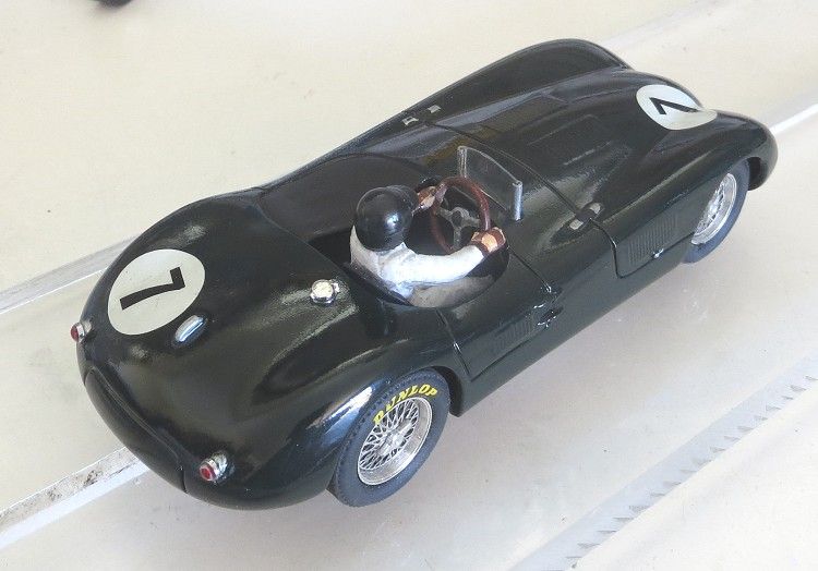
Paint colour is a 50:50 black and dark green mix.
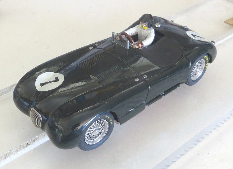
Fly screen home made cut from a clear Ninco gear packet and some fine brass tube. Sand through the side of the tube to reveal a slot the screen can slip into. The screen is glued in place with aeromodeller’s canopy cement, this dries clear. The photo etched grille is also glued in place.
The headlight recesses had a pair of 5 m.m. headlights glued into place. These lights, the tail lights and the fuel cap were supplied by Lagartija Kit
Lagartijakit
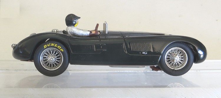
Wheels and tyres care of Pendle slot, made by Cartix and sold under the name MITOOS
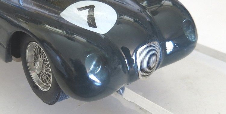
The headlight recesses were carefully filled with clear epoxy and carefully sanded back to match the body profile.
C types on eBay
I have counter weighted the rear of the model so that it is about two grams heavier than the front. I have found this measure, combined with a change of driving style, gets the model moving at a respectable speed and cornering (with secret formula urethane MJK tyres) as good as any model.
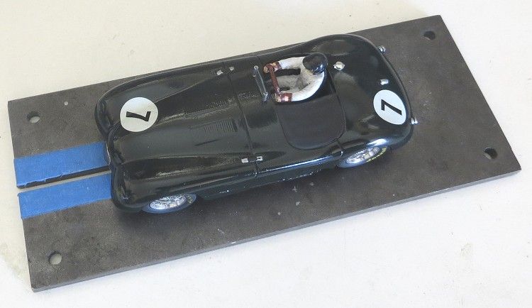
Total model weight is 88 grams which is around the upper limit for the motor installed. Another post build mod was with the guide. Most modern guides are about 1.6 m.m. thick. This is fine for fixed wheel front ends, but where steering is involved a wide slot, typically 3.0 m.m. on board tracks, and a thin guide will cause the model’s front wheels to run off centre in one direction or the other because of the sloppiness of the guide in the slot. To remedy this I have built up the leading and trailing edges of the guide up to 2.5 m.m. with superglue. I have deliberately left the centre of the guide free of glue as this may cause the guide to jam in some of the tighter inner turns.
As yet the finished model is yet to have some track time but I have run the bare chassis and steering on my local board track with promising results. This coming weekend will see how well it goes!
Stay tuned